
User Manual Owner's manual
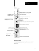
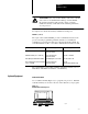
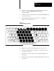
Table Of Contents
- 1772-6.5.8, Mini-PLC-2/02, -2/16, -2/17 Processor, User Manual
- Important User Information
- Summary of Changes
- Table of Contents
- 1 - Using This Manual
- 2 - Fundamentals of a Programmable Controller
- 3 - Hardware Features
- 4 - Installing Your Programmable Controller
- 5 - Starting Your Processor
- 6 - Maintaining and Troubleshooting Your Processor
- 7 - Memory Organization
- 8 - Scan Theory
- 9 - Relay-Like Instructions
- 10 - Program Control Instructions
- 11 - Timers and Counters
- 12 - Data Manipulation and Compare Instructions
- 13 - Three-Digit Math Instructions
- 14 - EAF Math Instructions
- 15 - EAF Log, Trig, and FIFO Instructions
- 16 - EAF Process Control Instructions
- 17 - Jump Instructions and Subroutines
- 18 - Block Transfer
- 19 - Data Transfer Instructions
- 20 - Bit Shift Registers
- 21 - Sequencers
- 22 - Selectable Timer Interrupts
- 23 - Report Generation
- 24 - Program Editing
- 25 - Programming Techniques
- 26 - Program Troubleshooting
- A - Specifications
- B - Processor Comparison Chart
- C - Number Systems
- D - Glossary
- E - Quick Reference
- Index
- Back Cover
Hardware Features
Chapter 3
3-5
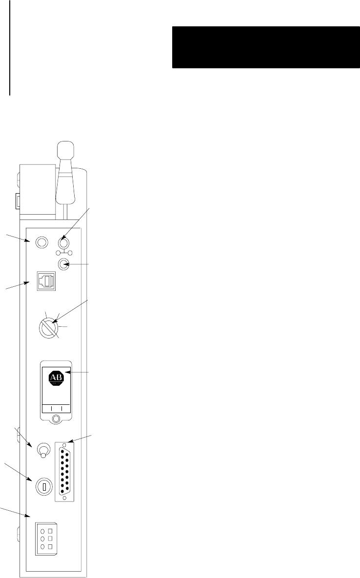
Figure 3.2
With
a Power Supply
PROC
F
A
U
L
T
R
U
N
BATT
INTFC
BATTERY
INSTALLED
MINI-PLC-2/17
RUN
R/P
MEM
STORE
PROC indicator lights green for normal operation and
red for a processor fault. Off indicates that you are in
Program Mode or a possible runtime error. You
reset this LED by cycling power.
BATT (Red) lights when battery should be replaced.
Key Switch selects one of four positions:
PROG: Program
R/P: Run/Program
RUN: Run
MEM STORE: Transfer program to MEM STORE backup EEPROM
Battery backup helps protect stored memory.
Interface Port allows you to connect
information sources such as a 1770T3
terminal, handheld terminal. Data Highway
or Report Generation module.
10295–I
W/POWER SUPPLY
POWER
ON
OFF
1A 250V
SLOW BLOW
120/220
V.A.C.
L1
L2/N
GND
P
R
O
G
P/S
ACTIVE
P
/
S
P
R
L
Line Voltage Selector Switch (located in rear)
Green LED lights for normal
power supply operation.
Port allows you to parallel the processor
power supply with another power supply
in the I/O chassis.
Toggle switch controls the
processor power supply.
Fuse holder for a 1A, 250V,
slowblow power supply fuse.
120/220VAC terminals:
L1 - Line
L2/N - Line (220V)/Neutral (120V)
GND - Ground Bus
Mode
Select Key Switch
You can place the processor in any one of three modes of operation or
program the EEPROM with the key switch located on the front of
the processor.