
User Manual Owner's manual

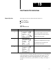
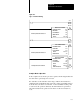
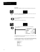
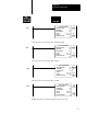
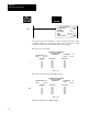
Table Of Contents
- 1772-6.5.8, Mini-PLC-2/02, -2/16, -2/17 Processor, User Manual
- Important User Information
- Summary of Changes
- Table of Contents
- 1 - Using This Manual
- 2 - Fundamentals of a Programmable Controller
- 3 - Hardware Features
- 4 - Installing Your Programmable Controller
- 5 - Starting Your Processor
- 6 - Maintaining and Troubleshooting Your Processor
- 7 - Memory Organization
- 8 - Scan Theory
- 9 - Relay-Like Instructions
- 10 - Program Control Instructions
- 11 - Timers and Counters
- 12 - Data Manipulation and Compare Instructions
- 13 - Three-Digit Math Instructions
- 14 - EAF Math Instructions
- 15 - EAF Log, Trig, and FIFO Instructions
- 16 - EAF Process Control Instructions
- 17 - Jump Instructions and Subroutines
- 18 - Block Transfer
- 19 - Data Transfer Instructions
- 20 - Bit Shift Registers
- 21 - Sequencers
- 22 - Selectable Timer Interrupts
- 23 - Report Generation
- 24 - Program Editing
- 25 - Programming Techniques
- 26 - Program Troubleshooting
- A - Specifications
- B - Processor Comparison Chart
- C - Number Systems
- D - Glossary
- E - Quick Reference
- Index
- Back Cover

Data Transfer File Instruction
Chapter 19
19-2
The word address defines:
the location in the data table to which or from which the data will
be moved.
this word address can be manipulated by ladder diagram logic
This instruction copies a source file and transfers it to the destination
file address.
It is programmed as an output instruction and requires 5 words of the
user program area.
The source file remains intact.
The counter is incremented internally by the instruction.
Internally
Indexed Counter
An internally indexed counter is incremented by the instruction itself. No
outside control is required. You assign an address to the counter.
An internally indexed file instruction has a done bit (15) and an enable bit
(17). These two bits are automatically entered from the counter address.
The enable bit is set when the rung logic goes from a false to true
transition; the done bit is set when the file instruction is completed.
When you look at Figure 19.2, notice that a value for rate per scan is
needed. The rate per scan defines the number of words that are operated
upon during one scan and is determined by the mode of operation.
FiletoFile Move Instruction