
User Manual Owner's manual
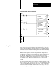
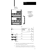
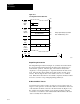
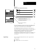
Table Of Contents
- 1772-6.5.8, Mini-PLC-2/02, -2/16, -2/17 Processor, User Manual
- Important User Information
- Summary of Changes
- Table of Contents
- 1 - Using This Manual
- 2 - Fundamentals of a Programmable Controller
- 3 - Hardware Features
- 4 - Installing Your Programmable Controller
- 5 - Starting Your Processor
- 6 - Maintaining and Troubleshooting Your Processor
- 7 - Memory Organization
- 8 - Scan Theory
- 9 - Relay-Like Instructions
- 10 - Program Control Instructions
- 11 - Timers and Counters
- 12 - Data Manipulation and Compare Instructions
- 13 - Three-Digit Math Instructions
- 14 - EAF Math Instructions
- 15 - EAF Log, Trig, and FIFO Instructions
- 16 - EAF Process Control Instructions
- 17 - Jump Instructions and Subroutines
- 18 - Block Transfer
- 19 - Data Transfer Instructions
- 20 - Bit Shift Registers
- 21 - Sequencers
- 22 - Selectable Timer Interrupts
- 23 - Report Generation
- 24 - Program Editing
- 25 - Programming Techniques
- 26 - Program Troubleshooting
- A - Specifications
- B - Processor Comparison Chart
- C - Number Systems
- D - Glossary
- E - Quick Reference
- Index
- Back Cover

Block Transfer
Chapter 18
18-24
Of these support rungs, buffering data must be programmed to ensure the
block transfer data is valid. Other techniques, such as an Immediate
Output instruction or a scan monitor, can also be programmed. The IOT
instruction requests a block transfer more than once per scan by assigning
it the output word address corresponding to the module’s location.
Program the IOT rung immediately following the block transfer rung. A
scan monitor monitors the number of scans that occurred between each
block transfer operation. For programming information on the scan
monitor, see the documentation for the block transfer module.
Also, if the number of words to be transferred or the location of block
transfer data must change at different times, special programming
techniques must be used.
Loading
Zeros
One rung that can be programmed is a Get/Put transfer (Figure 18.12). It
loads zeros into the timer/counter accumulated word, immediately
following the last block transfer Get address that identifies the module
location. The Get/Put transfer is programmed by selecting an unused
storage word for the Get instruction and entering zeros for its BCD value.
When a block transfer is requested, the processor starts at the first
timer/counter address and searches the timer/counter area until it finds the
module’s rack, group, and slot number or timer/counter address with all
zeros. By loading zeros into this consecutive Timer/Counter word
following the last Block Transfer instruction, the processor will not search
the remaining timer/counter area. In addition, the processor will not find
another BCD value that may, by chance, be the same number as the rack,
group or slot number.