
User Manual Owner's manual
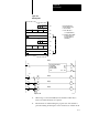
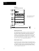
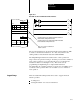
Table Of Contents
- 1772-6.5.8, Mini-PLC-2/02, -2/16, -2/17 Processor, User Manual
- Important User Information
- Summary of Changes
- Table of Contents
- 1 - Using This Manual
- 2 - Fundamentals of a Programmable Controller
- 3 - Hardware Features
- 4 - Installing Your Programmable Controller
- 5 - Starting Your Processor
- 6 - Maintaining and Troubleshooting Your Processor
- 7 - Memory Organization
- 8 - Scan Theory
- 9 - Relay-Like Instructions
- 10 - Program Control Instructions
- 11 - Timers and Counters
- 12 - Data Manipulation and Compare Instructions
- 13 - Three-Digit Math Instructions
- 14 - EAF Math Instructions
- 15 - EAF Log, Trig, and FIFO Instructions
- 16 - EAF Process Control Instructions
- 17 - Jump Instructions and Subroutines
- 18 - Block Transfer
- 19 - Data Transfer Instructions
- 20 - Bit Shift Registers
- 21 - Sequencers
- 22 - Selectable Timer Interrupts
- 23 - Report Generation
- 24 - Program Editing
- 25 - Programming Techniques
- 26 - Program Troubleshooting
- A - Specifications
- B - Processor Comparison Chart
- C - Number Systems
- D - Glossary
- E - Quick Reference
- Index
- Back Cover
Block Transfer
Chapter 18
18-22
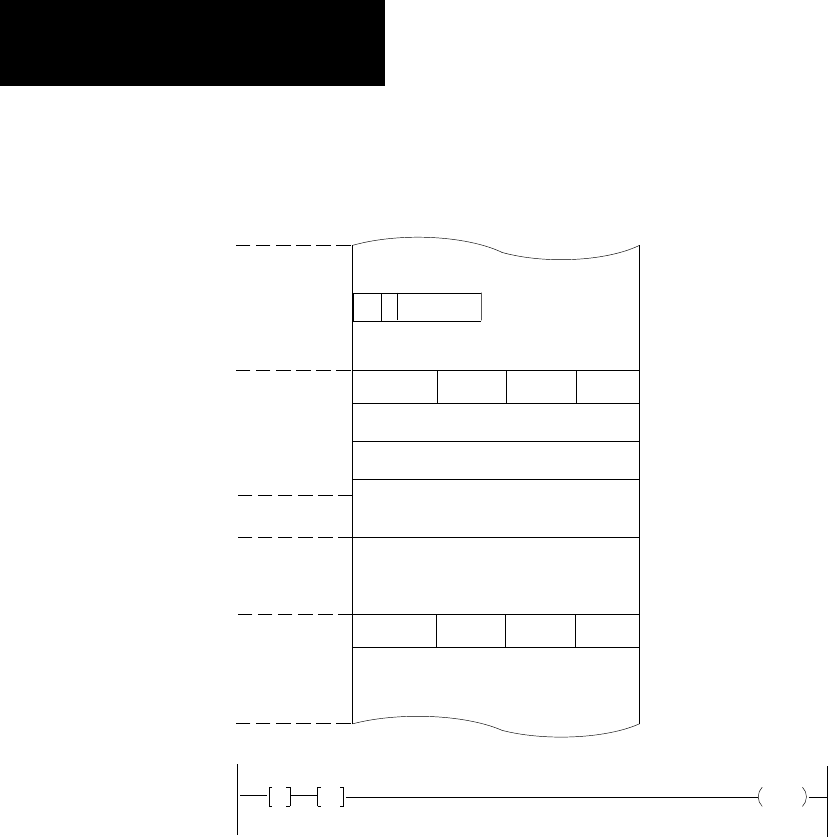
Figure 18.10
Selecting
Block Transfer Data Area
1
113
006
Block Transfer Data
010
013
027
060
067
110
127
130
030
Analog input module (8 bit) located in
Rack 1 Module Group 3, Slot 1
Output
Image
Table
Timer/
Counter
AC Area
Input
Image
Table
Timer/
Counter
PR Area
030
013
130
G
060
G
131
17
10382-I
Output Energize Instruction
The Output Energize instruction (Figure 18.9) initiates the block transfer.
It is given an address that indicates the module location and the type of
block transfer operation. The first digit of the address is always 0 for
output byte, even though an input or output block transfer module can be
used. The next three digits identify the module location by rack, group,
and slot. The last digit is either a 6 to enable a write or a 7 to enable a
read. When the block transfer is successfully completed, the Read or Write
done bit is set in the corresponding Input Image Table byte.
BiDirectional
Block T
ransfer
A bi-directional operation requires one rung for a read operation and one
rung for a write operation. Consecutive addresses in the timer/counter area
of the data table should be selected for the Get instructions (Figure 18.11).
For example, the first Get instruction of both rungs should be assigned
consecutive word addresses such as 030 and 031. Both will have the same
“data” to identify the module location.