
User Manual Owner's manual
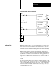
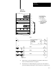
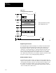
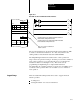
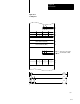
Table Of Contents
- 1772-6.5.8, Mini-PLC-2/02, -2/16, -2/17 Processor, User Manual
- Important User Information
- Summary of Changes
- Table of Contents
- 1 - Using This Manual
- 2 - Fundamentals of a Programmable Controller
- 3 - Hardware Features
- 4 - Installing Your Programmable Controller
- 5 - Starting Your Processor
- 6 - Maintaining and Troubleshooting Your Processor
- 7 - Memory Organization
- 8 - Scan Theory
- 9 - Relay-Like Instructions
- 10 - Program Control Instructions
- 11 - Timers and Counters
- 12 - Data Manipulation and Compare Instructions
- 13 - Three-Digit Math Instructions
- 14 - EAF Math Instructions
- 15 - EAF Log, Trig, and FIFO Instructions
- 16 - EAF Process Control Instructions
- 17 - Jump Instructions and Subroutines
- 18 - Block Transfer
- 19 - Data Transfer Instructions
- 20 - Bit Shift Registers
- 21 - Sequencers
- 22 - Selectable Timer Interrupts
- 23 - Report Generation
- 24 - Program Editing
- 25 - Programming Techniques
- 26 - Program Troubleshooting
- A - Specifications
- B - Processor Comparison Chart
- C - Number Systems
- D - Glossary
- E - Quick Reference
- Index
- Back Cover

Block Transfer
Chapter 18
18-20
module is loaded into words 050-052. When block transfer is
complete, done bit 114/07 is set in the input image table byte. This
indicates the block transfer was successfully performed. The
processor then continues with the I/O scan and program scan.
3. In rung 2, bit 114/07 is still on and a diagnostic bit is examined to
ensure the data read from the module is valid. Assuming the data is
valid, the diagnostic bit is on and the data is transferred from word
050 to 150. In rungs 3 and 4, the data in words 051 and 052 is
transferred to words 151 and 152 if the appropriate diagnostic bits
are on.
If you are using a 1770-T1 or -T2 industrial terminal to program a
processor and you want to perform block transfer, you must use the two
Get method.
The Block Transfer rung must be programmed in a certain format
(Figure 18.9). It consists of condition instructions that are optional, two
Get instructions and an Output Energize instruction.
Figure 18.9
Block
Transfer Rung
WYZ
0RGST
XYZ
G
ABC
G
RGS
optional
10389–I
conditions
Here is an explanation of the optional conditions:
This Condition: Examine the:
WYZ First timer/counter address (accumulated area).
XYZ Timer/counter address 100
8
higher than WYZ (preset area).
RGS Location of the block transfer module (I/O rack, module group. and
module slot. S is a zero for the left slot and a 1 for the right slot.
For a 2slot module, S is always zero.
ABC Starting address where data in transferred to/from.
0RGST Output energize initiates Block Transfer.
0 = output byte
R = rack
G = module group
S = module slot
T = 6 for write operation; 7 for read operation
Two Get Method