
User Manual Owner's manual
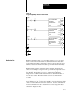
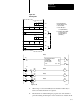
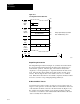
Table Of Contents
- 1772-6.5.8, Mini-PLC-2/02, -2/16, -2/17 Processor, User Manual
- Important User Information
- Summary of Changes
- Table of Contents
- 1 - Using This Manual
- 2 - Fundamentals of a Programmable Controller
- 3 - Hardware Features
- 4 - Installing Your Programmable Controller
- 5 - Starting Your Processor
- 6 - Maintaining and Troubleshooting Your Processor
- 7 - Memory Organization
- 8 - Scan Theory
- 9 - Relay-Like Instructions
- 10 - Program Control Instructions
- 11 - Timers and Counters
- 12 - Data Manipulation and Compare Instructions
- 13 - Three-Digit Math Instructions
- 14 - EAF Math Instructions
- 15 - EAF Log, Trig, and FIFO Instructions
- 16 - EAF Process Control Instructions
- 17 - Jump Instructions and Subroutines
- 18 - Block Transfer
- 19 - Data Transfer Instructions
- 20 - Bit Shift Registers
- 21 - Sequencers
- 22 - Selectable Timer Interrupts
- 23 - Report Generation
- 24 - Program Editing
- 25 - Programming Techniques
- 26 - Program Troubleshooting
- A - Specifications
- B - Processor Comparison Chart
- C - Number Systems
- D - Glossary
- E - Quick Reference
- Index
- Back Cover
Block Transfer
Chapter 18
18-19
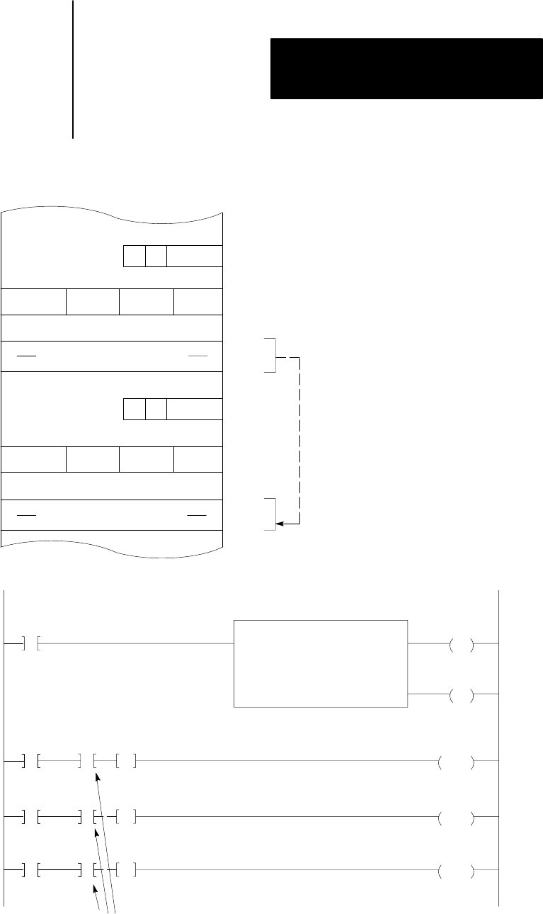
Figure 18.8
Buffering
Data
R
10
Block Length
Code
104
005
Block Transfer Data (Buffer)
Block Transfer Data (Valid)
R
10
014
030
050
052
114
130
150
152
EN
Block Transfer Read
Data Addr:
Module Addr:
Block Length:
File:
030
140
03
052
DN
PUT
010
07
152
333
Rung 4
07
PUT
010
02
150
111
Rung 2
PUT
010
02
151
222
Rung 3
111
11
Rung 1
014
07
050-
114
07
050
G
111
051
G
222
052
G
333
Diagnostic Bit
10228I
Data in the buffer file
050052 will be moved
to 150152 when:
A. Done Bit 114/07
is set (Valid transfer)
B. Diagnostic Bit is TRUE
for each word to be
moved in rungs 5-7
(valid data)
1. When rung 1 is true, bit 014/07 (the block transfer enable bit) is
turned on and block transfer is requested.
2. Block transfer is enabled during the program scan. The transfer is
performed during an interruption of the next I/O scan. Data from the