
User Manual Owner's manual
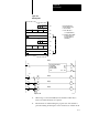
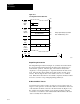
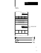
Table Of Contents
- 1772-6.5.8, Mini-PLC-2/02, -2/16, -2/17 Processor, User Manual
- Important User Information
- Summary of Changes
- Table of Contents
- 1 - Using This Manual
- 2 - Fundamentals of a Programmable Controller
- 3 - Hardware Features
- 4 - Installing Your Programmable Controller
- 5 - Starting Your Processor
- 6 - Maintaining and Troubleshooting Your Processor
- 7 - Memory Organization
- 8 - Scan Theory
- 9 - Relay-Like Instructions
- 10 - Program Control Instructions
- 11 - Timers and Counters
- 12 - Data Manipulation and Compare Instructions
- 13 - Three-Digit Math Instructions
- 14 - EAF Math Instructions
- 15 - EAF Log, Trig, and FIFO Instructions
- 16 - EAF Process Control Instructions
- 17 - Jump Instructions and Subroutines
- 18 - Block Transfer
- 19 - Data Transfer Instructions
- 20 - Bit Shift Registers
- 21 - Sequencers
- 22 - Selectable Timer Interrupts
- 23 - Report Generation
- 24 - Program Editing
- 25 - Programming Techniques
- 26 - Program Troubleshooting
- A - Specifications
- B - Processor Comparison Chart
- C - Number Systems
- D - Glossary
- E - Quick Reference
- Index
- Back Cover

Block Transfer
Chapter 18
18-18
One technique of buffering data is to store the transferred data in a
temporary buffer file. If the data in the buffer is valid, it is immediately
transferred to another file in the data table where it can be used. If invalid,
it is not transferred but written over in the next transfer.
Another technique uses only one file. The technique prevents invalid data
from being operated upon by preconditioning the rungs that would transfer
data out of a file one word at a time. Diagnostic and/or data-valid bits are
examined in these rungs.
Data can be moved from the buffer word-by-word using Get/Put transfers,
or the entire file can be moved at once using a File-to-File Move
instruction. The choice depends on the kinds of diagnostic and/or
data-valid bits and the objectives of the user program. Generally, when
one diagnostic bit is contained in each word, a get/put transfer is used.
When one is set for the entire file, a File-to-File Move instruction is used.
In either case, the diagnostic bits are examined as conditions for enabling
the file move or word transfer.
The example in Figure 18.8 shows the memory map and ladder diagram
rungs for buffering three words of data that are read from the block transfer
module. The data is read and buffered in the following sequence: