
User Manual Owner's manual
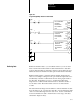
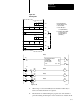
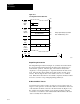
Table Of Contents
- 1772-6.5.8, Mini-PLC-2/02, -2/16, -2/17 Processor, User Manual
- Important User Information
- Summary of Changes
- Table of Contents
- 1 - Using This Manual
- 2 - Fundamentals of a Programmable Controller
- 3 - Hardware Features
- 4 - Installing Your Programmable Controller
- 5 - Starting Your Processor
- 6 - Maintaining and Troubleshooting Your Processor
- 7 - Memory Organization
- 8 - Scan Theory
- 9 - Relay-Like Instructions
- 10 - Program Control Instructions
- 11 - Timers and Counters
- 12 - Data Manipulation and Compare Instructions
- 13 - Three-Digit Math Instructions
- 14 - EAF Math Instructions
- 15 - EAF Log, Trig, and FIFO Instructions
- 16 - EAF Process Control Instructions
- 17 - Jump Instructions and Subroutines
- 18 - Block Transfer
- 19 - Data Transfer Instructions
- 20 - Bit Shift Registers
- 21 - Sequencers
- 22 - Selectable Timer Interrupts
- 23 - Report Generation
- 24 - Program Editing
- 25 - Programming Techniques
- 26 - Program Troubleshooting
- A - Specifications
- B - Processor Comparison Chart
- C - Number Systems
- D - Glossary
- E - Quick Reference
- Index
- Back Cover
Block Transfer
Chapter 18
18-17
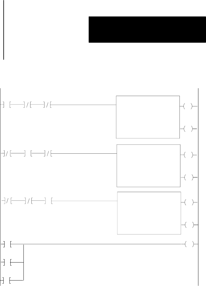
Figure 18.7
Programming
Multiple Reads from One Module
EN
BLOCK X FER READ
DATA ADDR:
MODULE ADDR:
BLOCK LENGTH:
FILE:
042
130
04
160163
DN
113
07
013
07
EN
BLOCK X FER READ
DATA ADDR:
MODULE ADDR:
BLOCK LENGTH:
FILE:
042
130
08
160167
DN
113
06
013
06
EN
BLOCK X FER READ
DATA ADDR:
MODULE ADDR:
BLOCK LENGTH:
FILE:
042
130
03
160162
DN
113
06
013
06
1
2
3
Inputs
1
2
3
Inputs
1
2
3
Inputs
1
014
17
Input
2
Input
3
Input
Buffer block transfer data so you can validate it before you use it. Data
that is read from the block transfer module and transferred to data table
locations must be buffered. Data that is written to the module need not be
buffered because block transfer modules perform this function internally.
Buffer transferred data to ensure that both the transfer and the data are
valid. As an example, readings from an open-circuited temperature sensor
(invalid data) could have a valid transfer from an analog input module to
the data table. Program the processor to examine data-valid and/or
diagnostic bits contained in the transferred data to determine whether or
not the data is valid. The block transfer done bit is set if the transfer
is valid.
The data-valid and/or diagnostic bits differ for each block transfer module.
Some modules set one or both for the entire file of words transferred, while
others set a data-valid diagnostic bit in each word. See the documentation
for the block transfer module to determine the correct usage of the data
valid and/or diagnostic bit(s).
Buffering Data