
User Manual Owner's manual
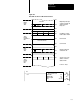
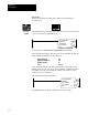
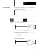
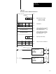
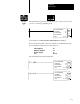
Table Of Contents
- 1772-6.5.8, Mini-PLC-2/02, -2/16, -2/17 Processor, User Manual
- Important User Information
- Summary of Changes
- Table of Contents
- 1 - Using This Manual
- 2 - Fundamentals of a Programmable Controller
- 3 - Hardware Features
- 4 - Installing Your Programmable Controller
- 5 - Starting Your Processor
- 6 - Maintaining and Troubleshooting Your Processor
- 7 - Memory Organization
- 8 - Scan Theory
- 9 - Relay-Like Instructions
- 10 - Program Control Instructions
- 11 - Timers and Counters
- 12 - Data Manipulation and Compare Instructions
- 13 - Three-Digit Math Instructions
- 14 - EAF Math Instructions
- 15 - EAF Log, Trig, and FIFO Instructions
- 16 - EAF Process Control Instructions
- 17 - Jump Instructions and Subroutines
- 18 - Block Transfer
- 19 - Data Transfer Instructions
- 20 - Bit Shift Registers
- 21 - Sequencers
- 22 - Selectable Timer Interrupts
- 23 - Report Generation
- 24 - Program Editing
- 25 - Programming Techniques
- 26 - Program Troubleshooting
- A - Specifications
- B - Processor Comparison Chart
- C - Number Systems
- D - Glossary
- E - Quick Reference
- Index
- Back Cover
Block Transfer
Chapter 18
18-14
Keystrokes
Enter a bi-directional block transfer (like this example) by performing the
following steps.
Block Transfer 0 appears in the lower left corner of the screen, above the
processor’s current programming mode.
BLOCK
XFER
1
EN
BLOCK X FER READ
DATA ADDR:
MODULE ADDR:
BLOCK LENGTH:
FILE:
030
100
01
110- 110
DN
110
07
010
07
The Block Transfer enable bit is 01007; the done bit is 11007.
Note that the words BLOCK TRANSFER READ are flashing.
Insert the following values. The cursor will block automatically step
through the block transfer write instruction. The values are:
DATA ADDRESS 030
MODULE ADDRESS 142
BLOCK LENGTH 05
FILE 060064
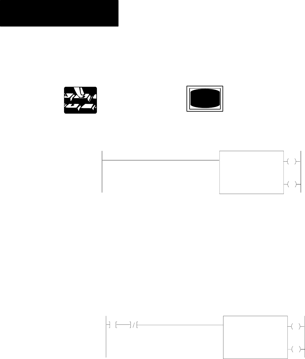
The write instruction should look like this:
EN
BLOCK X FER READ
DATA ADDR:
MODULE ADDR:
BLOCK LENGTH:
FILE:
042
30
05
070- 074
DN
113
07
013
07