
User Manual Owner's manual
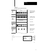
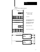
Table Of Contents
- 1772-6.5.8, Mini-PLC-2/02, -2/16, -2/17 Processor, User Manual
- Important User Information
- Summary of Changes
- Table of Contents
- 1 - Using This Manual
- 2 - Fundamentals of a Programmable Controller
- 3 - Hardware Features
- 4 - Installing Your Programmable Controller
- 5 - Starting Your Processor
- 6 - Maintaining and Troubleshooting Your Processor
- 7 - Memory Organization
- 8 - Scan Theory
- 9 - Relay-Like Instructions
- 10 - Program Control Instructions
- 11 - Timers and Counters
- 12 - Data Manipulation and Compare Instructions
- 13 - Three-Digit Math Instructions
- 14 - EAF Math Instructions
- 15 - EAF Log, Trig, and FIFO Instructions
- 16 - EAF Process Control Instructions
- 17 - Jump Instructions and Subroutines
- 18 - Block Transfer
- 19 - Data Transfer Instructions
- 20 - Bit Shift Registers
- 21 - Sequencers
- 22 - Selectable Timer Interrupts
- 23 - Report Generation
- 24 - Program Editing
- 25 - Programming Techniques
- 26 - Program Troubleshooting
- A - Specifications
- B - Processor Comparison Chart
- C - Number Systems
- D - Glossary
- E - Quick Reference
- Index
- Back Cover
Block Transfer
Chapter 18
18-13
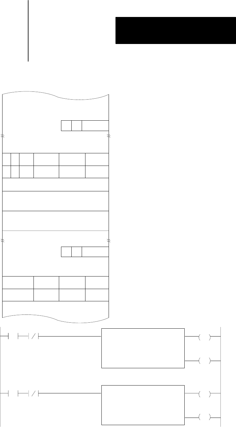
Figure 18.6
Data
T
able Locations for BiDirectional T
ransfer
R
11
103
Block Transfer Write File
11
013
040
041
060
070
113
140
141
013
W
RW
1
1031
Block Transfer Read File
007
006
5 words of data table are to be written
to the bidirectional block transfer
module starting from word
5 words of data are to be read from
the module and loaded into the data
table starting at word
Input Image Table Low Byte
07
10229I
Data Table
Block Length
Code
010
Output Image Table Low Byte
Data Addresses
Storage Locations of File Addresses
R = Bit 7 or 17 = Read
W = Bit 6 or 16 = Write
Block Transfer Read
Data Addr: 040
Module Addr:
Block Length:
File:
130
05
070074
113
07
EN
013
06
Block Transfer Write
Data Addr: 041
Module Addr:
Block Length:
File:
130
05
060064
113
06
EN
DN
EN
060
8
070
8