
User Manual Owner's manual
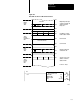
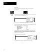
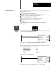
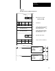
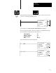
Table Of Contents
- 1772-6.5.8, Mini-PLC-2/02, -2/16, -2/17 Processor, User Manual
- Important User Information
- Summary of Changes
- Table of Contents
- 1 - Using This Manual
- 2 - Fundamentals of a Programmable Controller
- 3 - Hardware Features
- 4 - Installing Your Programmable Controller
- 5 - Starting Your Processor
- 6 - Maintaining and Troubleshooting Your Processor
- 7 - Memory Organization
- 8 - Scan Theory
- 9 - Relay-Like Instructions
- 10 - Program Control Instructions
- 11 - Timers and Counters
- 12 - Data Manipulation and Compare Instructions
- 13 - Three-Digit Math Instructions
- 14 - EAF Math Instructions
- 15 - EAF Log, Trig, and FIFO Instructions
- 16 - EAF Process Control Instructions
- 17 - Jump Instructions and Subroutines
- 18 - Block Transfer
- 19 - Data Transfer Instructions
- 20 - Bit Shift Registers
- 21 - Sequencers
- 22 - Selectable Timer Interrupts
- 23 - Report Generation
- 24 - Program Editing
- 25 - Programming Techniques
- 26 - Program Troubleshooting
- A - Specifications
- B - Processor Comparison Chart
- C - Number Systems
- D - Glossary
- E - Quick Reference
- Index
- Back Cover

Block Transfer
Chapter 18
18-12
You can enter data directly into the block to be transferred. Position the
cursor over the block transfer instruction and press [Display] [1]. See
chapter 9.
Bi-directional block transfer is the sequential performance of both
operations. The order of operation is generally determined by the module.
Two data addresses must be used. In this example they are 030 and 031.
Both contain the module address. For bi-directional operation, each data
address word also contains an enable bit:
bit 16 for a Write operation (in 031)
bit 17 for a Read operation (in 030)
Important: These bits are automatically set by the Block Transfer Read
and Write instructions.
When the processor searches the data addresses in the timer/counter
accumulated area of the data table, it finds two consecutive data addresses
both containing the same module address. The read bit and the write bit
are set in two consecutive data addresses. When the processor finds a
match of the module address and the read or write enable bit (read bit or
write bit) for the desired direction of transfer, it then locates the file
addresses to which (or from which) the data will be transferred.
Figure 18.6 shows an example bi-directional block transfer.
BiDirectional Block Transfer