
User Manual Owner's manual
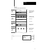
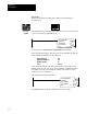
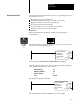
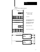
Table Of Contents
- 1772-6.5.8, Mini-PLC-2/02, -2/16, -2/17 Processor, User Manual
- Important User Information
- Summary of Changes
- Table of Contents
- 1 - Using This Manual
- 2 - Fundamentals of a Programmable Controller
- 3 - Hardware Features
- 4 - Installing Your Programmable Controller
- 5 - Starting Your Processor
- 6 - Maintaining and Troubleshooting Your Processor
- 7 - Memory Organization
- 8 - Scan Theory
- 9 - Relay-Like Instructions
- 10 - Program Control Instructions
- 11 - Timers and Counters
- 12 - Data Manipulation and Compare Instructions
- 13 - Three-Digit Math Instructions
- 14 - EAF Math Instructions
- 15 - EAF Log, Trig, and FIFO Instructions
- 16 - EAF Process Control Instructions
- 17 - Jump Instructions and Subroutines
- 18 - Block Transfer
- 19 - Data Transfer Instructions
- 20 - Bit Shift Registers
- 21 - Sequencers
- 22 - Selectable Timer Interrupts
- 23 - Report Generation
- 24 - Program Editing
- 25 - Programming Techniques
- 26 - Program Troubleshooting
- A - Specifications
- B - Processor Comparison Chart
- C - Number Systems
- D - Glossary
- E - Quick Reference
- Index
- Back Cover
Block Transfer
Chapter 18
18-7
Unequal Block Lengths
Consult the documentation for the block transfer module for programming
guidelines when setting the block lengths to unequal values.
ATTENTION: When the block lengths of bi-directional block
transfer instructions are set to unequal values, the rung
containing the alternate instruction must not be enabled until the
done bit of the first transfer is set. If they are enabled in the
same scan, the number of words transferred may not be the
number intended, invalid data could be operated upon in
subsequent scans, or analog output devices could be controlled
by invalid data. Unexpected and/or hazardous machine
operation could occur. Damage to equipment and/or personal
injury could result.
File
Address
The file address is the first word of the file to which (or from which) the
transfer is made. The file address is stored 100
8
words above the data
address of the instruction. When the file address is entered into the
instruction block, the industrial terminal computes and displays the ending
address based on the block length.
When reserving an area for a block transfer file, an appropriate address
must be selected to ensure that block transfer data does not write over
assigned timer/counter accumulated and preset values. The file address
cannot exceed address 3577 for a Mini-PLC-2/02, 7577 for a
Mini-PLC-2/16, or 17177 for a Mini-PLC-2/17.
Enable/Done Bit
The read and write bits are the enable bits for block transfer modules.
Either one (or both for a bi-directional transfer) is set on in the program
scan when the rung containing the block transfer instruction is true.
The done bit is set on in the I/O scan that the words are transferred,
provided that the transfer was initiated and successfully completed. The
done bit remains on for only one scan.
A block transfer is requested in each program scan that the read and/or
write bit remains on. The read and/or write bits are turned off when the
rung containing the instruction goes false.