
User Manual Owner's manual
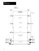
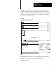
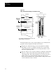
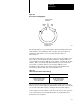
Table Of Contents
- 1772-6.5.8, Mini-PLC-2/02, -2/16, -2/17 Processor, User Manual
- Important User Information
- Summary of Changes
- Table of Contents
- 1 - Using This Manual
- 2 - Fundamentals of a Programmable Controller
- 3 - Hardware Features
- 4 - Installing Your Programmable Controller
- 5 - Starting Your Processor
- 6 - Maintaining and Troubleshooting Your Processor
- 7 - Memory Organization
- 8 - Scan Theory
- 9 - Relay-Like Instructions
- 10 - Program Control Instructions
- 11 - Timers and Counters
- 12 - Data Manipulation and Compare Instructions
- 13 - Three-Digit Math Instructions
- 14 - EAF Math Instructions
- 15 - EAF Log, Trig, and FIFO Instructions
- 16 - EAF Process Control Instructions
- 17 - Jump Instructions and Subroutines
- 18 - Block Transfer
- 19 - Data Transfer Instructions
- 20 - Bit Shift Registers
- 21 - Sequencers
- 22 - Selectable Timer Interrupts
- 23 - Report Generation
- 24 - Program Editing
- 25 - Programming Techniques
- 26 - Program Troubleshooting
- A - Specifications
- B - Processor Comparison Chart
- C - Number Systems
- D - Glossary
- E - Quick Reference
- Index
- Back Cover
Block Transfer
Chapter 18
18-3
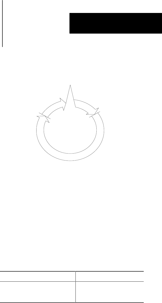
Figure 18.2
Block
T
ransfer T
iming Diagram
Transfer is made
in I/O Scan
Output
Scan
Input
Scan
Request is made in
Program Scan
10377-I
The module address is stored in the timer/counter accumulated area in the
same manner as an accumulated value of a timer. The word address at
which the module address is stored is called the data address of
the instruction.
Once the module address is found, the processor locates the address of the
file to which (or from which) the data is transferred. The file address is
stored in BCD at an address 100
8
above the address containing the module
address. This is done in the same manner that the processor locates the
preset value of a timer/counter in a word address 100
8
above the
accumulated value address. The analogy between block transfer and
timer/counter data and addresses is shown in Table 18.A.
Table 18.A
T
imer and Counter Block Transfer Analogy
Timer/Counter Block Transfer
Address of Accumulated Value
Accumulated Value in BCD
Address of Preset Value
Preset Value of BCD
Data Address of Instruction
Module Address in BCD
100
8
Above Data Address
File Address in BCD
After locating the file address in the preset timer/counter area of the data
table, the processor then duplicates and transfers the file data consecutively
one word at a time until complete, starting at the selected file address.
At the completion of the transfer, a done bit for the read or write operation
is set in the status byte in the input image table as a signal that a valid
transfer has been completed.