
User Manual Owner's manual
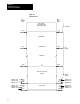
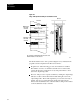
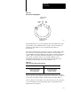
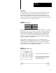
Table Of Contents
- 1772-6.5.8, Mini-PLC-2/02, -2/16, -2/17 Processor, User Manual
- Important User Information
- Summary of Changes
- Table of Contents
- 1 - Using This Manual
- 2 - Fundamentals of a Programmable Controller
- 3 - Hardware Features
- 4 - Installing Your Programmable Controller
- 5 - Starting Your Processor
- 6 - Maintaining and Troubleshooting Your Processor
- 7 - Memory Organization
- 8 - Scan Theory
- 9 - Relay-Like Instructions
- 10 - Program Control Instructions
- 11 - Timers and Counters
- 12 - Data Manipulation and Compare Instructions
- 13 - Three-Digit Math Instructions
- 14 - EAF Math Instructions
- 15 - EAF Log, Trig, and FIFO Instructions
- 16 - EAF Process Control Instructions
- 17 - Jump Instructions and Subroutines
- 18 - Block Transfer
- 19 - Data Transfer Instructions
- 20 - Bit Shift Registers
- 21 - Sequencers
- 22 - Selectable Timer Interrupts
- 23 - Report Generation
- 24 - Program Editing
- 25 - Programming Techniques
- 26 - Program Troubleshooting
- A - Specifications
- B - Processor Comparison Chart
- C - Number Systems
- D - Glossary
- E - Quick Reference
- Index
- Back Cover

Chapter
18
18-1
Block Transfer
This chapter describes 3 types of block transfer:
read
write
bi-directional
Block transfer is a combination of an instruction and support rungs used to
transfer as many as 64 16-bit words of data in one scan from I/O modules
to/from the data table. This transfer method is used by intelligent I/O
modules such as the analog, PID, servo positioning, stepper positioning,
ASCII, thermocouple, or encoder/counter modules.
Block transfer can be performed as a read, write, or bi-directional
operation, depending on the I/O module you are using. An input module
uses the read operation, an output module uses the write operations.
During a read operation, data is read into the data table from the module.
During a write operation, data is written to the output module from the
data table.
The processor uses two I/O image table bytes to communicate with block
transfer modules. The byte corresponding to the module’s address in the
output image table (control byte) contains the read or write bit for initiating
the transfer of data. The byte corresponding to the module’s address in the
input image table (status byte) is used to signal the completion of
the transfer.
Important: Do not use word 127 for data storage. Block transfer requires
the output image table byte and the corresponding input image table byte.
Word 127 cannot be used since its corresponding image table byte, word
027, contains the processor status bits.
Whether the upper or lower byte of the I/O image table word is used
depends on the position of the module in the module group. When the
module is in the left slot, the lower byte is used and vice versa
(Figure 18.1).
Chapter Objectives
Basic Operation