
User Manual Owner's manual
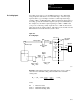
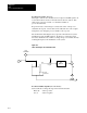
Table Of Contents
- 1772-6.5.8, Mini-PLC-2/02, -2/16, -2/17 Processor, User Manual
- Important User Information
- Summary of Changes
- Table of Contents
- 1 - Using This Manual
- 2 - Fundamentals of a Programmable Controller
- 3 - Hardware Features
- 4 - Installing Your Programmable Controller
- 5 - Starting Your Processor
- 6 - Maintaining and Troubleshooting Your Processor
- 7 - Memory Organization
- 8 - Scan Theory
- 9 - Relay-Like Instructions
- 10 - Program Control Instructions
- 11 - Timers and Counters
- 12 - Data Manipulation and Compare Instructions
- 13 - Three-Digit Math Instructions
- 14 - EAF Math Instructions
- 15 - EAF Log, Trig, and FIFO Instructions
- 16 - EAF Process Control Instructions
- 17 - Jump Instructions and Subroutines
- 18 - Block Transfer
- 19 - Data Transfer Instructions
- 20 - Bit Shift Registers
- 21 - Sequencers
- 22 - Selectable Timer Interrupts
- 23 - Report Generation
- 24 - Program Editing
- 25 - Programming Techniques
- 26 - Program Troubleshooting
- A - Specifications
- B - Processor Comparison Chart
- C - Number Systems
- D - Glossary
- E - Quick Reference
- Index
- Back Cover

EAF
Process Control Instructions
Chapter 16
16-29
Input Format Bit (Word 01, Bit 07)
Allows the Process Variable (PV) and Tieback (TB) to be input in Binary
or BCD (series C or later).
Reset (0) PV and TB are in Binary
Set (1) PV and TB are in BCD
Integral Gain (Word 05)
When using the Independent Gain Equation, this value is the integral gain
constant K
I
(rep/sec). When using the Dependent Gains Equation, this
value is equal to T
I
(min/rep).
K
I
x10(Word 02, Bit 00)
When using the Independent Gains Equation. Set this bit to move the
implied decimal point of K
I
to the right (for example 0.10 converts
to 1.00).
Reset (0) decimal point not moved
Set (1) decimal moved one place to the right
K
D
/10 (Word 02, Bit 01)
When using the Independent Gains equation, set this bit to move the
implied decimal point of K
D
to the left (for example, 10.0 converts to
1.00). This improves the resolution of this term.
Reset (0) decimal point not moved
Set (1) decimal moved one place to the left
Manual Control Station
A manual control station is a hardware device used to control the output
directly and override the PID instruction’s output. The use of a manual
control station is optional. Set Output mode allows the same features
without this hardware device (See Set Output). When using a manual
control station, feed the manually controlled output value into the PID
instruction’s tieback (TB) input. The PID instruction uses this value
(0 to 4095) to calculate the integral term value required to achieve a
bumpless transfer when switching from manual to automatic control.
Maximum Output Alarm (Word 01, Bit 11)
This bit is set by the EAF instruction whenever the computed Control
Output goes above the limit set by Maximum Control Output (word 12).
Mode (Word 01, Bit 01)
Set/reset this bit to choose either Automatic or Manual mode. A hardwired
auto/manual station would manipulate this bit.
Reset (0) Automatic
Set (1) Manual