
User Manual Owner's manual
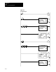
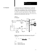
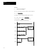
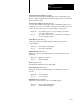
Table Of Contents
- 1772-6.5.8, Mini-PLC-2/02, -2/16, -2/17 Processor, User Manual
- Important User Information
- Summary of Changes
- Table of Contents
- 1 - Using This Manual
- 2 - Fundamentals of a Programmable Controller
- 3 - Hardware Features
- 4 - Installing Your Programmable Controller
- 5 - Starting Your Processor
- 6 - Maintaining and Troubleshooting Your Processor
- 7 - Memory Organization
- 8 - Scan Theory
- 9 - Relay-Like Instructions
- 10 - Program Control Instructions
- 11 - Timers and Counters
- 12 - Data Manipulation and Compare Instructions
- 13 - Three-Digit Math Instructions
- 14 - EAF Math Instructions
- 15 - EAF Log, Trig, and FIFO Instructions
- 16 - EAF Process Control Instructions
- 17 - Jump Instructions and Subroutines
- 18 - Block Transfer
- 19 - Data Transfer Instructions
- 20 - Bit Shift Registers
- 21 - Sequencers
- 22 - Selectable Timer Interrupts
- 23 - Report Generation
- 24 - Program Editing
- 25 - Programming Techniques
- 26 - Program Troubleshooting
- A - Specifications
- B - Processor Comparison Chart
- C - Number Systems
- D - Glossary
- E - Quick Reference
- Index
- Back Cover

EAF
Process Control Instructions
Chapter 16
16-26
Cascade (Word 01, Bit 05)
Set/reset this bit for cascading two loops. When the bit is set, the loop is
the secondary (fast) loop of the cascade. When the bit is reset, the loop is
the primary (slow) loop of the cascade or not part of a
cascade configuration.
Control Action (Word 01, Bit 02)
Set/Reset this bit to change the control action for the PID calculation.
Direct Control Bit Reset (0) E = (SP – PV)
Reverse Control Bit Set (1) E = (PV – SP)
CO (Control Output) (EAF Result Address and Parameter File Word 17)
This is the result of the evaluation of the PID equation. It is expressed in
two formats. In the EAF result address, it is a binary number (0-4095). In
the parameter file (word 17), it is a percentage in BCD format (0-100).
This number is converted to a signal that drives a control device such as a
valve or heating element.
Control Output Tracking
It is desirable to make the CO equal to the output of the manual control
station when in the manual mode. This allows a bumpless transfer
between Manual and Auto modes. This is accomplished by feeding the
output of the manual control station into the tieback (TB) input. The
instruction sets the calculated CO equal to the TB input when in
manual mode.
Dead Band (Word 10)
The adjustable deadband lets you select an error range above and below the
setpoint over which no new output will be calculated as long as the Process
Variable remains within this range. This lets you control how closely the
process variable matches the setpoint without changing the output.
The Dead Band operates using the zero crossing principle. Zero Crossing
Dead Band control allows the instruction to use the error for computational
purposes as the process variable crosses into the Dead Band until it crosses
the Set Point. Once it crosses the Set Point (error crosses zero and changes
sign) and as long as it remains in the Dead Band, the instruction considers
the error value zero for computational purposes.
Dead Band Status Bit (Bit 10 of word 01)
This bit is set/reset by the PID EAF instruction indicating whether the
process variable is within or out of the Dead Band.
Reset (0) Outside of the Dead Band
Set (1) Within the Dead Band