
User Manual Owner's manual
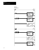
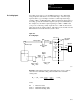
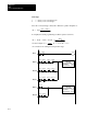
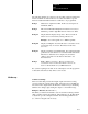
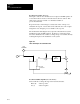
Table Of Contents
- 1772-6.5.8, Mini-PLC-2/02, -2/16, -2/17 Processor, User Manual
- Important User Information
- Summary of Changes
- Table of Contents
- 1 - Using This Manual
- 2 - Fundamentals of a Programmable Controller
- 3 - Hardware Features
- 4 - Installing Your Programmable Controller
- 5 - Starting Your Processor
- 6 - Maintaining and Troubleshooting Your Processor
- 7 - Memory Organization
- 8 - Scan Theory
- 9 - Relay-Like Instructions
- 10 - Program Control Instructions
- 11 - Timers and Counters
- 12 - Data Manipulation and Compare Instructions
- 13 - Three-Digit Math Instructions
- 14 - EAF Math Instructions
- 15 - EAF Log, Trig, and FIFO Instructions
- 16 - EAF Process Control Instructions
- 17 - Jump Instructions and Subroutines
- 18 - Block Transfer
- 19 - Data Transfer Instructions
- 20 - Bit Shift Registers
- 21 - Sequencers
- 22 - Selectable Timer Interrupts
- 23 - Report Generation
- 24 - Program Editing
- 25 - Programming Techniques
- 26 - Program Troubleshooting
- A - Specifications
- B - Processor Comparison Chart
- C - Number Systems
- D - Glossary
- E - Quick Reference
- Index
- Back Cover

EAF
Process Control Instructions
Chapter 16
16-21
This list identifies the function of the ladder diagram symbols.
110/00 Manual Push Button
110/01 Auto Push Button
110/02 Enter Push Button
320/04 Set-Output bit
332 PID Set-Output value
115/00 Manual Override Output Value
340 PID CO Value
Figure 16.7 shows how you can cascade two loops by assigning the control
output (CO) of one loop as the set point (SP) of the next loop. Locate
these rungs in the main program. Set the cascade bit (word 01, bit 05) of
the inner loop so that it will interpret the outer loops properly.
Setting the cascade bit forces the set point of the secondary loop to accept
0 to 4095 binary. This allows the output of the primary loop to be moved
directly into the set point of the secondary loop.
Cascading Loops