
User Manual Owner's manual
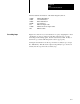
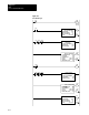
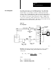
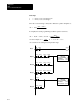
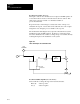
Table Of Contents
- 1772-6.5.8, Mini-PLC-2/02, -2/16, -2/17 Processor, User Manual
- Important User Information
- Summary of Changes
- Table of Contents
- 1 - Using This Manual
- 2 - Fundamentals of a Programmable Controller
- 3 - Hardware Features
- 4 - Installing Your Programmable Controller
- 5 - Starting Your Processor
- 6 - Maintaining and Troubleshooting Your Processor
- 7 - Memory Organization
- 8 - Scan Theory
- 9 - Relay-Like Instructions
- 10 - Program Control Instructions
- 11 - Timers and Counters
- 12 - Data Manipulation and Compare Instructions
- 13 - Three-Digit Math Instructions
- 14 - EAF Math Instructions
- 15 - EAF Log, Trig, and FIFO Instructions
- 16 - EAF Process Control Instructions
- 17 - Jump Instructions and Subroutines
- 18 - Block Transfer
- 19 - Data Transfer Instructions
- 20 - Bit Shift Registers
- 21 - Sequencers
- 22 - Selectable Timer Interrupts
- 23 - Report Generation
- 24 - Program Editing
- 25 - Programming Techniques
- 26 - Program Troubleshooting
- A - Specifications
- B - Processor Comparison Chart
- C - Number Systems
- D - Glossary
- E - Quick Reference
- Index
- Back Cover

EAF
Process Control Instructions
Chapter 16
16-20
Rungs An additional group of PID instructions would cause the
16 – 21 STI to exceed its allowed limit (33 ms for a 50 ms
interrupt). This is the first four of a second group of eight
PID instructions. They execute on the opposite scan from
the first group of eight PID instructions so that the timing
limit is not exceeded.
Rungs The second four PID instructions of the second group of
22 – 27 PID instructions. They execute on the opposite scan from
the first group of eight PID instructions.
Figure 16.6 shows how you can simulate a manual control station. Locate
these rungs in the main program. This program will be used when the
functionality of a hardware manual control station is desired but manual
control separate from the controlling processor is not needed. It uses set
output mode to write the manual override output value to the
control device.
Figure 16.6
This
Is a Simulated Manual Station
EN
BLOCK XFER READ
DATA ADDR:
MODULE ADDR:
BLOCK LENGTH:
FILE:
0030
110
01
0200-0200
110
00
L
320
OFF 04
110
01
U
320
0115
000
G
320
04
110
02
PUT
0332
000
04
320 0340
075
G
PUT
0332
000
15
045
011
07
DN
111
07
15
045
TON
0045
.01
PR 110
AC 000
EXECUTE AUX
FUNCTION NUMBER:
DATA ADDR:
RESULT ADDR:
27
0200
0231
FUNCTION
111
07
0251
000
G
0200
550
G
EN
BLOCK XFER WRITE
DATA ADDR:
MODULE ADDR:
BLOCK LENGTH:
FILE:
0031
121
01
0231-0231
012
16
DN
112
16
OFF 04
Software Manual
Control Station