
User Manual Owner's manual
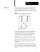
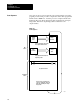
Table Of Contents
- 1772-6.5.8, Mini-PLC-2/02, -2/16, -2/17 Processor, User Manual
- Important User Information
- Summary of Changes
- Table of Contents
- 1 - Using This Manual
- 2 - Fundamentals of a Programmable Controller
- 3 - Hardware Features
- 4 - Installing Your Programmable Controller
- 5 - Starting Your Processor
- 6 - Maintaining and Troubleshooting Your Processor
- 7 - Memory Organization
- 8 - Scan Theory
- 9 - Relay-Like Instructions
- 10 - Program Control Instructions
- 11 - Timers and Counters
- 12 - Data Manipulation and Compare Instructions
- 13 - Three-Digit Math Instructions
- 14 - EAF Math Instructions
- 15 - EAF Log, Trig, and FIFO Instructions
- 16 - EAF Process Control Instructions
- 17 - Jump Instructions and Subroutines
- 18 - Block Transfer
- 19 - Data Transfer Instructions
- 20 - Bit Shift Registers
- 21 - Sequencers
- 22 - Selectable Timer Interrupts
- 23 - Report Generation
- 24 - Program Editing
- 25 - Programming Techniques
- 26 - Program Troubleshooting
- A - Specifications
- B - Processor Comparison Chart
- C - Number Systems
- D - Glossary
- E - Quick Reference
- Index
- Back Cover
Fundamentals of a
Programmable Controller
Chapter 2
2-9
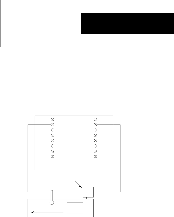
Let’s look at a simple example to see the sequence of events that take place
in controlling a machine with a programmable controller (Figure 2.1).
Suppose you are making a part. The motor driven conveyor carries a unit
to the work area. The limit switch detects wen the part arrives at the work
area. when that happens, we want the conveyor to stop so you can work on
the part.
Figure 2.1
A
Simplified Example of a Machine with a Programmable Controller
Conveyor
Motor
Limit
Switch
Conveyor
Unit
Controller
Input Output
11594
Notice how the limit switch and motor are wired to the programmable
controller. The limit switch, wired to terminal 02, is normally-closed. The
arriving part will open the switch. Therefore, the program statement
controlling the conveyor motor must read: “If there is voltage at input
terminal 02 (limit switch), then energize output terminal 02 (conveyer
motor).” The conveyor motor is wired to output terminal 02.
Important: Figure 2.1 is for demonstration purposes only. We do not
show the associated wiring, a motor starter, or an emergency stop button.
Since the limit switch is wired normally-closed, the conveyor motor runs
until the arriving part opens the switch. At that time, the condition for
energizing the motor is not longer met. Therefore, the motor is
de-energized.
When the condition is met, we say it is true. When the condition is not
met, we say it is false. There may be more than one condition which must
be met before an action is executed. When all the conditions are met, the
action is executed and we say the statement is true. When one or more of
the conditions are false, the action is not executed and we say the statement
is false.
Control Sequence