
User Manual Owner's manual
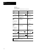
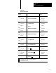
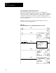
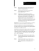
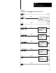
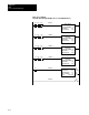
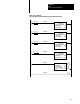
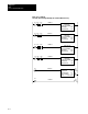
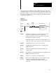
Table Of Contents
- 1772-6.5.8, Mini-PLC-2/02, -2/16, -2/17 Processor, User Manual
- Important User Information
- Summary of Changes
- Table of Contents
- 1 - Using This Manual
- 2 - Fundamentals of a Programmable Controller
- 3 - Hardware Features
- 4 - Installing Your Programmable Controller
- 5 - Starting Your Processor
- 6 - Maintaining and Troubleshooting Your Processor
- 7 - Memory Organization
- 8 - Scan Theory
- 9 - Relay-Like Instructions
- 10 - Program Control Instructions
- 11 - Timers and Counters
- 12 - Data Manipulation and Compare Instructions
- 13 - Three-Digit Math Instructions
- 14 - EAF Math Instructions
- 15 - EAF Log, Trig, and FIFO Instructions
- 16 - EAF Process Control Instructions
- 17 - Jump Instructions and Subroutines
- 18 - Block Transfer
- 19 - Data Transfer Instructions
- 20 - Bit Shift Registers
- 21 - Sequencers
- 22 - Selectable Timer Interrupts
- 23 - Report Generation
- 24 - Program Editing
- 25 - Programming Techniques
- 26 - Program Troubleshooting
- A - Specifications
- B - Processor Comparison Chart
- C - Number Systems
- D - Glossary
- E - Quick Reference
- Index
- Back Cover

EAF
Process Control Instructions
Chapter 16
16-14
Figure 16.4 shows you how to enter and display an STI to execute a
controlled PID function. The program that follows is programmed
specifically for 1771-IE, -IF, -OF, -IX and -IY modules. For the
1771-IFE, -IL and -IR modules, add the module initialization rungs in the
main program (see Figure 16.5).
The processor executes 16 PID loops with an update time of 100 ms. Eight
loops are executed each alternate scan (50 ms STI): the first 8 on scan 1,
the second 8 on scan 2, the first 8 on scan 3, the second 8 on scan 4. Since
the PID instruction needs a leading edge transition to execute
(false-to-true), you must use the alternate scan method even if you use less
than 8 loops.
The Immediate Output Update (IOT) instructions are required. Place them
after each block transfer instruction. The IOT instructions cause the block
transfer to be requested and completed immediately, instead of at the next
program scan. The address of the IOT is the same as the address of the
block transfer enable bit.
Observe there is no data buffering on the Block Transfer Read (BTR)
instruction. The BTR done bit cannot be made to report predictably in the
STI. Therefore, it can’t be used to buffer data.
If you want to program less than 16 loops, eliminate a PID EAF rung.
However, once you have eliminated four EAF rungs, you must eliminate
the associated Block Transfer Write (BTW) and IOT instructions.
Place an unconditionally false File-to-File instruction in the main program
to display the configuration of the PID loops.
Entry and Display of a
Selectable Timed Interrupt
(STI) Controlled PID Function