
User Manual Owner's manual
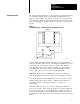
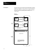
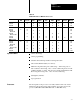
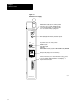
Table Of Contents
- 1772-6.5.8, Mini-PLC-2/02, -2/16, -2/17 Processor, User Manual
- Important User Information
- Summary of Changes
- Table of Contents
- 1 - Using This Manual
- 2 - Fundamentals of a Programmable Controller
- 3 - Hardware Features
- 4 - Installing Your Programmable Controller
- 5 - Starting Your Processor
- 6 - Maintaining and Troubleshooting Your Processor
- 7 - Memory Organization
- 8 - Scan Theory
- 9 - Relay-Like Instructions
- 10 - Program Control Instructions
- 11 - Timers and Counters
- 12 - Data Manipulation and Compare Instructions
- 13 - Three-Digit Math Instructions
- 14 - EAF Math Instructions
- 15 - EAF Log, Trig, and FIFO Instructions
- 16 - EAF Process Control Instructions
- 17 - Jump Instructions and Subroutines
- 18 - Block Transfer
- 19 - Data Transfer Instructions
- 20 - Bit Shift Registers
- 21 - Sequencers
- 22 - Selectable Timer Interrupts
- 23 - Report Generation
- 24 - Program Editing
- 25 - Programming Techniques
- 26 - Program Troubleshooting
- A - Specifications
- B - Processor Comparison Chart
- C - Number Systems
- D - Glossary
- E - Quick Reference
- Index
- Back Cover

Fundamentals of a
Programmable Controller
Chapter 2
2-8
Output Modules
The output modules of a programmable controller have four functions:
termination
indication
conditioning
isolation
Termination
The output provides terminals for the field wiring going to the output
devices on the machine.
Indication
The output of most modules provides a visual indication of the selected
state of each output device with LED indicators. The output status
indicator is on when the output device is energized. A common term
applied to either input status indicators or output status indicators is I/O
status indicators. I/O stands for either input or output.
In older modules, when power is present at the output terminals, the status
indicators are ON. In high density modules, power may not be present at
the output terminals for the status indicator to be ON.
Conditioning
The output conditions the programmable controller’s signals for the
machine. That is, it converts the low-level dc voltages of the
programmable controller to the type of electrical power used by the output
devices at the machine.
Isolation
The output isolates the circuitry of the programmable controller from
unwanted and dangerous voltages that occasionally occur at the machine
or the plant’s wiring system. Some situations require additional
external protection.
Power
Supply
The power supply provides low-level dc voltage for the electronic circuitry
of the processor, its input and output modules. It converts line voltages to
the lower logic voltages required by the processor and its input and
output modules.