
User Manual Owner's manual
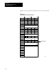
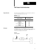
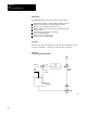
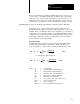
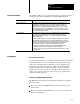
Table Of Contents
- 1772-6.5.8, Mini-PLC-2/02, -2/16, -2/17 Processor, User Manual
- Important User Information
- Summary of Changes
- Table of Contents
- 1 - Using This Manual
- 2 - Fundamentals of a Programmable Controller
- 3 - Hardware Features
- 4 - Installing Your Programmable Controller
- 5 - Starting Your Processor
- 6 - Maintaining and Troubleshooting Your Processor
- 7 - Memory Organization
- 8 - Scan Theory
- 9 - Relay-Like Instructions
- 10 - Program Control Instructions
- 11 - Timers and Counters
- 12 - Data Manipulation and Compare Instructions
- 13 - Three-Digit Math Instructions
- 14 - EAF Math Instructions
- 15 - EAF Log, Trig, and FIFO Instructions
- 16 - EAF Process Control Instructions
- 17 - Jump Instructions and Subroutines
- 18 - Block Transfer
- 19 - Data Transfer Instructions
- 20 - Bit Shift Registers
- 21 - Sequencers
- 22 - Selectable Timer Interrupts
- 23 - Report Generation
- 24 - Program Editing
- 25 - Programming Techniques
- 26 - Program Troubleshooting
- A - Specifications
- B - Processor Comparison Chart
- C - Number Systems
- D - Glossary
- E - Quick Reference
- Index
- Back Cover

EAF
Process Control Instructions
Chapter 16
16-5
The number of PID loops, loop update time, and type of input and output
modules are important considerations for using the PID instruction.
Consideration: Description:
Number of PID loops The number of PID loops that a MiniPLC2/17 processor can handle depends on
the update time required by the loops. The longer the update time and the less
sophisticated the loop control, the more loops can be controlled. Typically, when
programmed in the selectable timed interrupt subroutine, the processor can control
16 loops which have a 100 ms loop update time. You can also program slower loops
in the main ladder program. The PID instruction is a timebased calculation which
can be triggered with timer done bits.
Loop update time The PID instruction calculates a new control output (CO) whenever its rung changes
from false to true. The PID instruction is a timebased calculation. Trigger the
calculation with either timer done bits or a selectable timed interrupt subroutine to
control its update time.
In order for the PID instruction to operate predictably, the update time (term that you
entered in word 14) must be equal to the rate at which the PID rung is toggled. The
rung will be toggled at the timing value of the timer (preset x time base) or each time
value of the STI. Deviation in toggle rate from the update time will degrade the
accuracy of PID calculations. To get the accuracy suited to your process:
• Program loops with fast response time in the selectable timed interrupt (STI)
subroutine along with their corresponding block transfer instructions.
• Program slower response loops in the main ladder program using timers to control
the update time.
Block
T
ransfer Instructions
Use block transfer instructions to transfer data between analog I/O modules
and the PID instruction. Use a block transfer read instruction for input
values, Process Variable (PV), and Tieback Use a block transfer write
instruction for the Control Output (CO). Make each block transfer file
address (Data File entry) the same address that you enter in the PID
instruction respectively for the Process Variable, Tieback, and Control
Output. Also, enter the module’s location (rack, group, and module) in
each block transfer instruction.
PID Instruction Input/Output Data Format
The PID instruction must access its PV (input) and deliver its output in a
particular format:
The series A and series B Mini-PLC-2/17 processor must use 12-bit
binary format
The series C (and later) Mini-PLC-2/17 processor lets you select 12-bit
binary or 4-digit BCD.
Loop Considerations
Programming