
User Manual Owner's manual
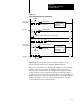
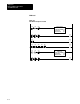
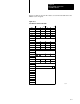
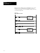
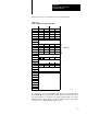
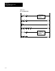
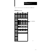
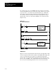
Table Of Contents
- 1772-6.5.8, Mini-PLC-2/02, -2/16, -2/17 Processor, User Manual
- Important User Information
- Summary of Changes
- Table of Contents
- 1 - Using This Manual
- 2 - Fundamentals of a Programmable Controller
- 3 - Hardware Features
- 4 - Installing Your Programmable Controller
- 5 - Starting Your Processor
- 6 - Maintaining and Troubleshooting Your Processor
- 7 - Memory Organization
- 8 - Scan Theory
- 9 - Relay-Like Instructions
- 10 - Program Control Instructions
- 11 - Timers and Counters
- 12 - Data Manipulation and Compare Instructions
- 13 - Three-Digit Math Instructions
- 14 - EAF Math Instructions
- 15 - EAF Log, Trig, and FIFO Instructions
- 16 - EAF Process Control Instructions
- 17 - Jump Instructions and Subroutines
- 18 - Block Transfer
- 19 - Data Transfer Instructions
- 20 - Bit Shift Registers
- 21 - Sequencers
- 22 - Selectable Timer Interrupts
- 23 - Report Generation
- 24 - Program Editing
- 25 - Programming Techniques
- 26 - Program Troubleshooting
- A - Specifications
- B - Processor Comparison Chart
- C - Number Systems
- D - Glossary
- E - Quick Reference
- Index
- Back Cover
EAF Logarithmic, Trigonometric
and FIFO Instructions
Chapter 15
15-16
If you want to keep zero as valid FIFO data, leave the bit set and it will
progress through the file as any other word would. However, if you want
to get rid of zero, you could reset the bit with ladder logic. The Result
Word will not reflect the change until the next data is transferred into or
out of the file. The zeros are then over-written. Valid data moves up to
take the place of the zeros when either a FIFO Load or Unload executes
(Figure 15.15).
Figure 15.15
Zero
Has Been Eliminated
130
EXECUTE AUX
FUNCTION
FUNCTION NUMBER:
DATA ADDR:
RESULT ADDR:
28
030
050
050 060
000
G
040
000
G
041
000
G
042
000
G
043
000
G
01 15
030
G
031 032
060
G
040 005
G ( )
070
00
050
000
G
( )
070
00
044
000
G
( )
070
00
130
EXECUTE AUX
FUNCTION
FUNCTION NUMBER:
DATA ADDR:
RESULT ADDR:
29
033
050
050 061
000
G
01 14
033
G
034 035
061
G
040 005
G
( )
070
00
FIFO Unload
Figure 15.16 shows data unloaded from the file into the Output Word. Bit
16 of the output word follows the condition of the FIFO Unload rung. Bit
16 is set (1) if the rung is true. Bit 16 is reset (0) if the rung is false.
Observe that 111 was the first data in the file and it is the first data out or
first in – first out (FIFO). Also, the Result Word has decremented by one.
It now shows four indicating that there are now four words in the file.