
User Manual Owner's manual
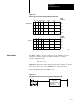
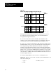
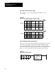
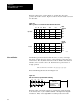
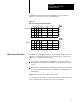
Table Of Contents
- 1772-6.5.8, Mini-PLC-2/02, -2/16, -2/17 Processor, User Manual
- Important User Information
- Summary of Changes
- Table of Contents
- 1 - Using This Manual
- 2 - Fundamentals of a Programmable Controller
- 3 - Hardware Features
- 4 - Installing Your Programmable Controller
- 5 - Starting Your Processor
- 6 - Maintaining and Troubleshooting Your Processor
- 7 - Memory Organization
- 8 - Scan Theory
- 9 - Relay-Like Instructions
- 10 - Program Control Instructions
- 11 - Timers and Counters
- 12 - Data Manipulation and Compare Instructions
- 13 - Three-Digit Math Instructions
- 14 - EAF Math Instructions
- 15 - EAF Log, Trig, and FIFO Instructions
- 16 - EAF Process Control Instructions
- 17 - Jump Instructions and Subroutines
- 18 - Block Transfer
- 19 - Data Transfer Instructions
- 20 - Bit Shift Registers
- 21 - Sequencers
- 22 - Selectable Timer Interrupts
- 23 - Report Generation
- 24 - Program Editing
- 25 - Programming Techniques
- 26 - Program Troubleshooting
- A - Specifications
- B - Processor Comparison Chart
- C - Number Systems
- D - Glossary
- E - Quick Reference
- Index
- Back Cover

EAF Math Instructions
Chapter 14
14-21
Enter a Binary number. Entry of the binary number FFF produces the
BCD number 004 095. If you enter 7FFF (use SEARCH 53 and set the
bits), 32 767 is displayed. All negative values are stored as two’s
complement. Figure 14.24 shows how the result is stored in the data table.
Bit 16 of the first Result Address word is the sign bit of the BCD number.
Figure 14.24
EAF
Binary to BCD Conversion Format in the Data T
able After Execution
17 16 15 14 10 7 4 3
Data
Address
0
Result
Address
10360-I
13
060
061
040
04
F
0
5
0
9
00 0 F F
X
0
Operand A
Result