
User Manual Owner's manual
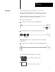
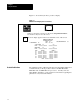
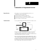
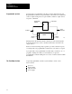
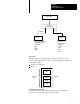
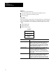
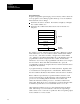
Table Of Contents
- 1772-6.5.8, Mini-PLC-2/02, -2/16, -2/17 Processor, User Manual
- Important User Information
- Summary of Changes
- Table of Contents
- 1 - Using This Manual
- 2 - Fundamentals of a Programmable Controller
- 3 - Hardware Features
- 4 - Installing Your Programmable Controller
- 5 - Starting Your Processor
- 6 - Maintaining and Troubleshooting Your Processor
- 7 - Memory Organization
- 8 - Scan Theory
- 9 - Relay-Like Instructions
- 10 - Program Control Instructions
- 11 - Timers and Counters
- 12 - Data Manipulation and Compare Instructions
- 13 - Three-Digit Math Instructions
- 14 - EAF Math Instructions
- 15 - EAF Log, Trig, and FIFO Instructions
- 16 - EAF Process Control Instructions
- 17 - Jump Instructions and Subroutines
- 18 - Block Transfer
- 19 - Data Transfer Instructions
- 20 - Bit Shift Registers
- 21 - Sequencers
- 22 - Selectable Timer Interrupts
- 23 - Report Generation
- 24 - Program Editing
- 25 - Programming Techniques
- 26 - Program Troubleshooting
- A - Specifications
- B - Processor Comparison Chart
- C - Number Systems
- D - Glossary
- E - Quick Reference
- Index
- Back Cover

Fundamentals of a
Programmable Controller
Chapter 2
2-5
I/O Image Tables
The input image table reflects the status of the input terminals. The output
image table reflects the status of bits controlled by the program.
Each image table is divided into a number of smaller units called bits. A
bit is the smallest unit of memory. A bit is a tiny electronic circuit that the
processor can turn on or off. Bits in the image table are associated with a
particular I/O terminal in the input or output section.
When the processor detects a voltage at an input terminal, it records that
information by turning the corresponding bit on. Likewise, when the
processor detects no voltage at an input terminal, it records that
information by turning the corresponding bit off. If, while executing your
program, the CPU decides that a particular output terminal should be
turned on or off, it records that decision by turning the corresponding bit
on or off. In other words, each bit in the I/O image tables corresponds to
the on or off status of an I/O terminal.
When people who work with personal computers talk about turning a bit
on, they use the term “set.” For example - “The processor sets the bit”
means “turns it on.” On the other hand, we use the term “reset” when we
talk about turning the bit off - for example, “The processor reset the bit.”
Picture memory as a page that has been divided into many blocks. Each
block represents one bit. Since each bit is either on or off, we could show
the state of each bit by writing “on” or “off” in each block. However, there
is an easier way. We can agree that the numeral one (1) means on and that
the numeral zero (0) means off. We can show the status of each bit by
writing 1 or 0 into the appropriate block. For example, you might hear
expressions like, “The CPU responded by writing a one into the bit when
the limit switch closed.” Of course, the processor didn’t really write a one
into memory: it simply set the bit by turning it on.
When the I/O device is: The bit status is said to be:
on
on
1
set
off
off
0
reset
If you heard the expression, “The processor wrote a zero into that bit
location.” What actually happened? If you said the processor merely reset
the bit by turning it off, you’re right.