
User Manual Owner's manual
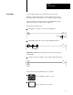
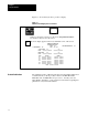
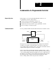
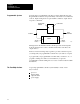
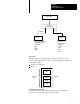
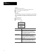
Table Of Contents
- 1772-6.5.8, Mini-PLC-2/02, -2/16, -2/17 Processor, User Manual
- Important User Information
- Summary of Changes
- Table of Contents
- 1 - Using This Manual
- 2 - Fundamentals of a Programmable Controller
- 3 - Hardware Features
- 4 - Installing Your Programmable Controller
- 5 - Starting Your Processor
- 6 - Maintaining and Troubleshooting Your Processor
- 7 - Memory Organization
- 8 - Scan Theory
- 9 - Relay-Like Instructions
- 10 - Program Control Instructions
- 11 - Timers and Counters
- 12 - Data Manipulation and Compare Instructions
- 13 - Three-Digit Math Instructions
- 14 - EAF Math Instructions
- 15 - EAF Log, Trig, and FIFO Instructions
- 16 - EAF Process Control Instructions
- 17 - Jump Instructions and Subroutines
- 18 - Block Transfer
- 19 - Data Transfer Instructions
- 20 - Bit Shift Registers
- 21 - Sequencers
- 22 - Selectable Timer Interrupts
- 23 - Report Generation
- 24 - Program Editing
- 25 - Programming Techniques
- 26 - Program Troubleshooting
- A - Specifications
- B - Processor Comparison Chart
- C - Number Systems
- D - Glossary
- E - Quick Reference
- Index
- Back Cover
Fundamentals of a
Programmable Controller
Chapter 2
2-4
Memory
Memory serves three functions:
stores information in the data table that the CPU may need
stores sets of instructions called a program
stores messages
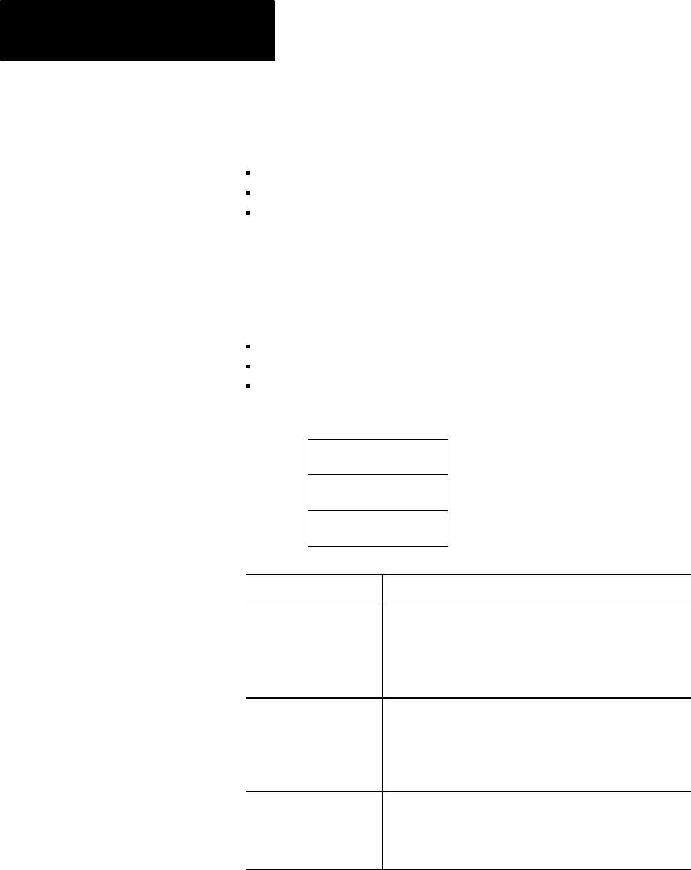
Data Table
The area of memory where data is controlled and used, is called the data
table. The data table is divided into several smaller sections according to
the type of information to be remembered. These smaller sections are
called:
output image table
input image table
timer/counter storage
Output Image Table
Input Image Table
Timer/Counter
Storage
Data Table
This memory area:
Serves this purpose:
output image tables The output image table controls the on or off status of the
output devices wired to the output module's terminals. If an
output image table bit is ON (1), its corresponding output
device is ON (energized). If a bit is OFF (0), its corresponding
output device is OFF (deenergized). Output image table bits
are controlled by the user's program.
input image tables The input image table duplicates the on or off status of the
input devices. If an input device is ON (closed), its
corresponding input image table bit is ON (1). If an input
image table bit is OFF (open), its corresponding input image
table bit is OFF (0). Input image table bits are monitored by the
user's program.
timer/counter storage Timer and Counter instructions are output instructions. They
provide many of the capabilities available with timing relays
and solidstate timing and counting devices. Usually
conditioned by examine instructions, they keep track of timed
intervals or counted events according to the logic of the rung.