
User Manual Owner's manual
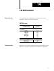
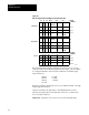
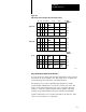
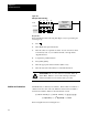
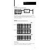
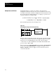
Table Of Contents
- 1772-6.5.8, Mini-PLC-2/02, -2/16, -2/17 Processor, User Manual
- Important User Information
- Summary of Changes
- Table of Contents
- 1 - Using This Manual
- 2 - Fundamentals of a Programmable Controller
- 3 - Hardware Features
- 4 - Installing Your Programmable Controller
- 5 - Starting Your Processor
- 6 - Maintaining and Troubleshooting Your Processor
- 7 - Memory Organization
- 8 - Scan Theory
- 9 - Relay-Like Instructions
- 10 - Program Control Instructions
- 11 - Timers and Counters
- 12 - Data Manipulation and Compare Instructions
- 13 - Three-Digit Math Instructions
- 14 - EAF Math Instructions
- 15 - EAF Log, Trig, and FIFO Instructions
- 16 - EAF Process Control Instructions
- 17 - Jump Instructions and Subroutines
- 18 - Block Transfer
- 19 - Data Transfer Instructions
- 20 - Bit Shift Registers
- 21 - Sequencers
- 22 - Selectable Timer Interrupts
- 23 - Report Generation
- 24 - Program Editing
- 25 - Programming Techniques
- 26 - Program Troubleshooting
- A - Specifications
- B - Processor Comparison Chart
- C - Number Systems
- D - Glossary
- E - Quick Reference
- Index
- Back Cover

EAF Math Instructions
Chapter 14
14-4
Bits 14-17 of the result word are reserved for status bits:
This
Bit:
Stores this:
14 overflow/underflow
1indicates overflow/underflow
0result is in range
15 zero indicator
1zero result
0nonzero result
16 sign bit
1negative ()
0positive (+)
17 not used
Data
T
able Format After Address Entry
If you select a data address of 040 for operand A, the EAF establishes a
data table format with four consecutive words as shown in Figure 14.2.
You can locate the result word anywhere in your data table. However, four
consecutive word addresses must be available. If you select an address of
060 for the result, the EAF automatically reserves 061, 062 and 063.
Be careful not to select data and result addresses so that they overlap.