
User Manual Owner's manual
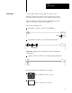
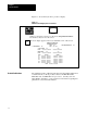
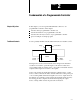
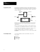
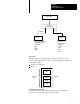
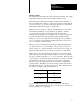
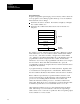
Table Of Contents
- 1772-6.5.8, Mini-PLC-2/02, -2/16, -2/17 Processor, User Manual
- Important User Information
- Summary of Changes
- Table of Contents
- 1 - Using This Manual
- 2 - Fundamentals of a Programmable Controller
- 3 - Hardware Features
- 4 - Installing Your Programmable Controller
- 5 - Starting Your Processor
- 6 - Maintaining and Troubleshooting Your Processor
- 7 - Memory Organization
- 8 - Scan Theory
- 9 - Relay-Like Instructions
- 10 - Program Control Instructions
- 11 - Timers and Counters
- 12 - Data Manipulation and Compare Instructions
- 13 - Three-Digit Math Instructions
- 14 - EAF Math Instructions
- 15 - EAF Log, Trig, and FIFO Instructions
- 16 - EAF Process Control Instructions
- 17 - Jump Instructions and Subroutines
- 18 - Block Transfer
- 19 - Data Transfer Instructions
- 20 - Bit Shift Registers
- 21 - Sequencers
- 22 - Selectable Timer Interrupts
- 23 - Report Generation
- 24 - Program Editing
- 25 - Programming Techniques
- 26 - Program Troubleshooting
- A - Specifications
- B - Processor Comparison Chart
- C - Number Systems
- D - Glossary
- E - Quick Reference
- Index
- Back Cover
Fundamentals of a
Programmable Controller
Chapter 2
2-3
Power Supply
Processor
Information
Limit, Proximity, Pressure,
Action
(Decision Making)
•
Temperature Switches
Push Buttons
Logic
BCD
Analog
•
•
•
•
Solenoids•
Motor Starters
Indicators
Alarms
Logic
BCD
Analog
•
•
•
•
•
•
Input Output
Processor
The first section of a programmable controller is the processor. The
processor might be called the “brains” of the programmable controller. It
is divided into halves:
central processing unit
memory
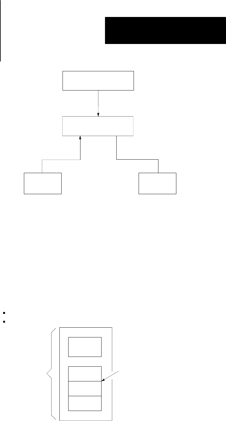
CPU
Data
Table
Program
Storage
Message
Storage
Memory
Processor
Section
Central Processing Unit
The Central Processor Unit (CPU) makes decisions about what the
processor does according to the program you write.