
User Manual Owner's manual
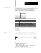
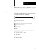
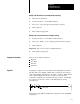
Table Of Contents
- 1772-6.5.8, Mini-PLC-2/02, -2/16, -2/17 Processor, User Manual
- Important User Information
- Summary of Changes
- Table of Contents
- 1 - Using This Manual
- 2 - Fundamentals of a Programmable Controller
- 3 - Hardware Features
- 4 - Installing Your Programmable Controller
- 5 - Starting Your Processor
- 6 - Maintaining and Troubleshooting Your Processor
- 7 - Memory Organization
- 8 - Scan Theory
- 9 - Relay-Like Instructions
- 10 - Program Control Instructions
- 11 - Timers and Counters
- 12 - Data Manipulation and Compare Instructions
- 13 - Three-Digit Math Instructions
- 14 - EAF Math Instructions
- 15 - EAF Log, Trig, and FIFO Instructions
- 16 - EAF Process Control Instructions
- 17 - Jump Instructions and Subroutines
- 18 - Block Transfer
- 19 - Data Transfer Instructions
- 20 - Bit Shift Registers
- 21 - Sequencers
- 22 - Selectable Timer Interrupts
- 23 - Report Generation
- 24 - Program Editing
- 25 - Programming Techniques
- 26 - Program Troubleshooting
- A - Specifications
- B - Processor Comparison Chart
- C - Number Systems
- D - Glossary
- E - Quick Reference
- Index
- Back Cover
Timers and Counters
Chapter 11
11-7
A counter counts the number of events that occur and stores this count in
its accumulated value word. Counters can be located anywhere in the data
table. An event is defined as a false-to-true transition. Counter
instructions have no time base.. The last counter address for each is
listed below:
This Processor Has This Last
Timer/Counter Address:
MiniPLC2/02 3477
MiniPLC2/16 7477
MiniPLC2/17 17077
The upper four bits in the accumulated value (AC) word are status bits:
This
Bit:
Contains This Information:
14 Overflow/underflow bit. It is set when the AC value of the CTU instruction
exceeds 999 or when the AC value of the CTD instruction falls below 000.
15 Count complete bit. it is set when the AC value > PR value.
16 Enable bit for CTD instruction. It is set when the rung condition is true.
17 Enable bit for CTU instruction. It is set when the rung condition is true.
There are three types of counter instructions available with the controller:
up counter
down counter
counter reset
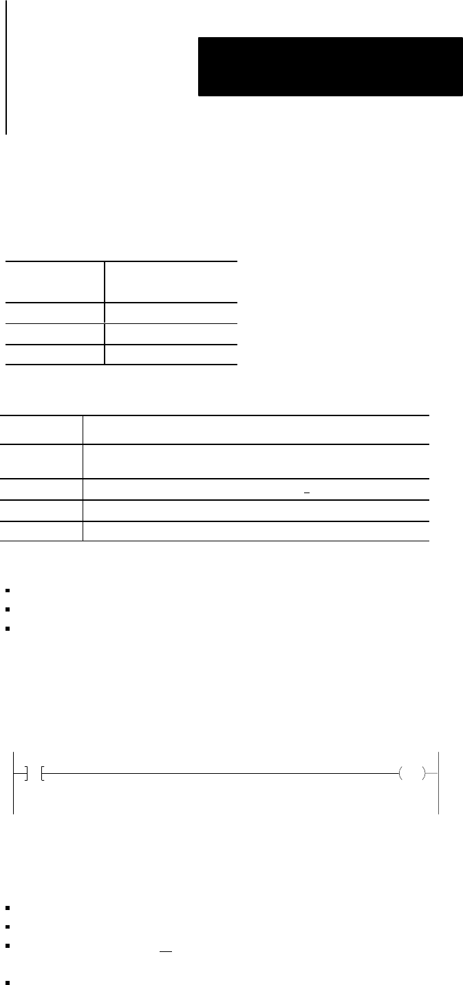
An Up Counter instruction increments its accumulated value for each
false-to-true transition of the rung condition. The rung condition must go
from true to false and back to true before the next count is registered.
010
00
CTU
030
PR 150
AC 000
When the rung condition becomes:
True
Accumulated value increments by 1.
Bit 14 is set if the AC > 999.
Bit 15 is set when AC > PR. Incrementing the accumulated value
continues after the preset value is reached.
Bit 17 is set and stays set until the rung goes false.
Counter Instructions
Up Counter