
User Manual Owner's manual
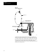
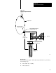
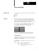
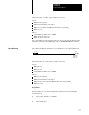
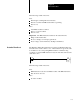
Table Of Contents
- 1772-6.5.8, Mini-PLC-2/02, -2/16, -2/17 Processor, User Manual
- Important User Information
- Summary of Changes
- Table of Contents
- 1 - Using This Manual
- 2 - Fundamentals of a Programmable Controller
- 3 - Hardware Features
- 4 - Installing Your Programmable Controller
- 5 - Starting Your Processor
- 6 - Maintaining and Troubleshooting Your Processor
- 7 - Memory Organization
- 8 - Scan Theory
- 9 - Relay-Like Instructions
- 10 - Program Control Instructions
- 11 - Timers and Counters
- 12 - Data Manipulation and Compare Instructions
- 13 - Three-Digit Math Instructions
- 14 - EAF Math Instructions
- 15 - EAF Log, Trig, and FIFO Instructions
- 16 - EAF Process Control Instructions
- 17 - Jump Instructions and Subroutines
- 18 - Block Transfer
- 19 - Data Transfer Instructions
- 20 - Bit Shift Registers
- 21 - Sequencers
- 22 - Selectable Timer Interrupts
- 23 - Report Generation
- 24 - Program Editing
- 25 - Programming Techniques
- 26 - Program Troubleshooting
- A - Specifications
- B - Processor Comparison Chart
- C - Number Systems
- D - Glossary
- E - Quick Reference
- Index
- Back Cover

Timers and Counters
Chapter 11
11-2
Preset Value (PR)
Storage begins at an address 100 words greater than its corresponding
AC value.
Function: Timers number of elapsed timed intervals
Counters number of counted events
Both when the accumulated value equals the preset
value, AC = PR, a status bit is set and can be
examined to turn an output device on or off.
A timer counts the elapsed time-base intervals and stores this count in the
accumulated value word. Timers can be anywhere in the data table. The
third digit from the right in the address must be an even number. Timer
instructions have three time bases: 1.0 second, 0.1 second, or 0.01 second.
Two bits in the accumulated value word are status bits:
Bit 15 is the timed (done) bit. It is set when the timer has timed out
(AC = PR). The setting or resetting depends on the type of
timer instruction.
Bit 17 is the enable bit. It is set when rung conditions are true and is
reset when rung conditions are false.
There are four types of timer instructions available:
timer on-delay
timer off-delay
retentive timer on-delay
retentive timer reset
The Timer On Delay instruction is programmed as an output instruction.
010
00
TON
030
1.0
PR 150
AC 000
Timer Instructions
Timer On Delay