
User Manual Owner's manual
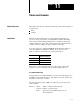
Table Of Contents
- 1772-6.5.8, Mini-PLC-2/02, -2/16, -2/17 Processor, User Manual
- Important User Information
- Summary of Changes
- Table of Contents
- 1 - Using This Manual
- 2 - Fundamentals of a Programmable Controller
- 3 - Hardware Features
- 4 - Installing Your Programmable Controller
- 5 - Starting Your Processor
- 6 - Maintaining and Troubleshooting Your Processor
- 7 - Memory Organization
- 8 - Scan Theory
- 9 - Relay-Like Instructions
- 10 - Program Control Instructions
- 11 - Timers and Counters
- 12 - Data Manipulation and Compare Instructions
- 13 - Three-Digit Math Instructions
- 14 - EAF Math Instructions
- 15 - EAF Log, Trig, and FIFO Instructions
- 16 - EAF Process Control Instructions
- 17 - Jump Instructions and Subroutines
- 18 - Block Transfer
- 19 - Data Transfer Instructions
- 20 - Bit Shift Registers
- 21 - Sequencers
- 22 - Selectable Timer Interrupts
- 23 - Report Generation
- 24 - Program Editing
- 25 - Programming Techniques
- 26 - Program Troubleshooting
- A - Specifications
- B - Processor Comparison Chart
- C - Number Systems
- D - Glossary
- E - Quick Reference
- Index
- Back Cover

Chapter
11
11-1
Timers and Counters
This chapter describes two instructions that keep track of timed intervals or
counted events:
timers
counters
Timer and counter instructions are output instructions internal to the
processor. They provide many of the capabilities available with timing
relays and solid state timing/counting devices. Usually conditioned by
examine instructions, timers and counters keep track of timed intervals or
counted events according to the logic continuity of the rung.
You can program up to 488 internal timers and the last timer address is
1677. The number of counters are limited only by the processor’s
memory. The last counter address for each is listed below:
This Processor Has This Last
Timer/Counter Address:
MiniPLC2/02 3477
MiniPLC2/16 7477
MiniPLC2/17 17077
Each timer or counter instruction has two 3-digit values. Each value
requires one word of data table memory. These 3-digit values are:
Accumulated Value (AC)
Storage begins at word address 030 in 2-slot and 1-slot addressing modes
and 050 in 1/2-slot addressing mode. The address of the AC value word is
the address of the timer or counter.
The AC value always starts at 000. Use status bit 15 of the AC word to
control outputs.
Function: Timers number of elapsed timed intervals
Counters number of counted events
Both upper 4 bits of accumulated word (14-17)
are the status bits.
Chapter Objectives
Introduction