
User Manual Owner's manual
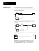
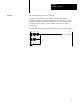
Table Of Contents
- 1772-6.5.8, Mini-PLC-2/02, -2/16, -2/17 Processor, User Manual
- Important User Information
- Summary of Changes
- Table of Contents
- 1 - Using This Manual
- 2 - Fundamentals of a Programmable Controller
- 3 - Hardware Features
- 4 - Installing Your Programmable Controller
- 5 - Starting Your Processor
- 6 - Maintaining and Troubleshooting Your Processor
- 7 - Memory Organization
- 8 - Scan Theory
- 9 - Relay-Like Instructions
- 10 - Program Control Instructions
- 11 - Timers and Counters
- 12 - Data Manipulation and Compare Instructions
- 13 - Three-Digit Math Instructions
- 14 - EAF Math Instructions
- 15 - EAF Log, Trig, and FIFO Instructions
- 16 - EAF Process Control Instructions
- 17 - Jump Instructions and Subroutines
- 18 - Block Transfer
- 19 - Data Transfer Instructions
- 20 - Bit Shift Registers
- 21 - Sequencers
- 22 - Selectable Timer Interrupts
- 23 - Report Generation
- 24 - Program Editing
- 25 - Programming Techniques
- 26 - Program Troubleshooting
- A - Specifications
- B - Processor Comparison Chart
- C - Number Systems
- D - Glossary
- E - Quick Reference
- Index
- Back Cover

Program Control Instruction
Chapter 10
10-2
A Master Control Reset (MCR) establishes a zone in the user program in
which all non-retentive outputs are turned off simultaneously.
Important: Retentive instructions (-(U)-, -(L)-, -(RTO)-) should not be
placed within an MCR zone, because the MCR zone maintains retentive
instructions in the last active state when the start fence goes false.
ATTENTION: A programmable controller should not be
operated without a hard-wired master control relay and
emergency stop switches to provide emergency I/O power
shutdown. Emergency stop switches can be monitored but
should not be controlled by the user program. These devices
should be wired as described in chapter 4. The purpose of the
devices is to guard against damage to equipment and/or injury
to personnel.
A Zone Control Last State (ZCL) instruction allows control of one or a
group of outputs in more than one manner in the same program. It
establishes a zone in the user program which controls the same outputs,
through separate rungs, at different times.
To override a group of output devices, you must use two MCR
(Figure 10.1) or ZCL (Figure 10.2) instructions: one each to begin the zone
and one each to end the zone. The start fence is always programmed with
a set of input conditions. The end fence must be programmed
unconditionally.
When the input conditions of the start fence of an MCR zone are false,
nonretentive outputs are turned off and held off. When the input
conditions of the start fence of a ZCL zone are false, all outputs within the
zone are left in their last state. The end fence must be programmed
unconditionally.