
User Manual Owner's manual
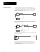
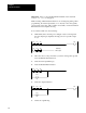
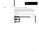
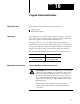
Table Of Contents
- 1772-6.5.8, Mini-PLC-2/02, -2/16, -2/17 Processor, User Manual
- Important User Information
- Summary of Changes
- Table of Contents
- 1 - Using This Manual
- 2 - Fundamentals of a Programmable Controller
- 3 - Hardware Features
- 4 - Installing Your Programmable Controller
- 5 - Starting Your Processor
- 6 - Maintaining and Troubleshooting Your Processor
- 7 - Memory Organization
- 8 - Scan Theory
- 9 - Relay-Like Instructions
- 10 - Program Control Instructions
- 11 - Timers and Counters
- 12 - Data Manipulation and Compare Instructions
- 13 - Three-Digit Math Instructions
- 14 - EAF Math Instructions
- 15 - EAF Log, Trig, and FIFO Instructions
- 16 - EAF Process Control Instructions
- 17 - Jump Instructions and Subroutines
- 18 - Block Transfer
- 19 - Data Transfer Instructions
- 20 - Bit Shift Registers
- 21 - Sequencers
- 22 - Selectable Timer Interrupts
- 23 - Report Generation
- 24 - Program Editing
- 25 - Programming Techniques
- 26 - Program Troubleshooting
- A - Specifications
- B - Processor Comparison Chart
- C - Number Systems
- D - Glossary
- E - Quick Reference
- Index
- Back Cover
RelayLike Instructions
Chapter 9
9-6
Editing
in a Completed Rung
Edit the Output Energize instruction by performing the following steps.
However, you cannot remove an output instruction.
1. Position the cursor over the Output Energize instruction you want
to change.
2. Press –( )– or any other appropriate output instruction key.
3. Enter <address>.
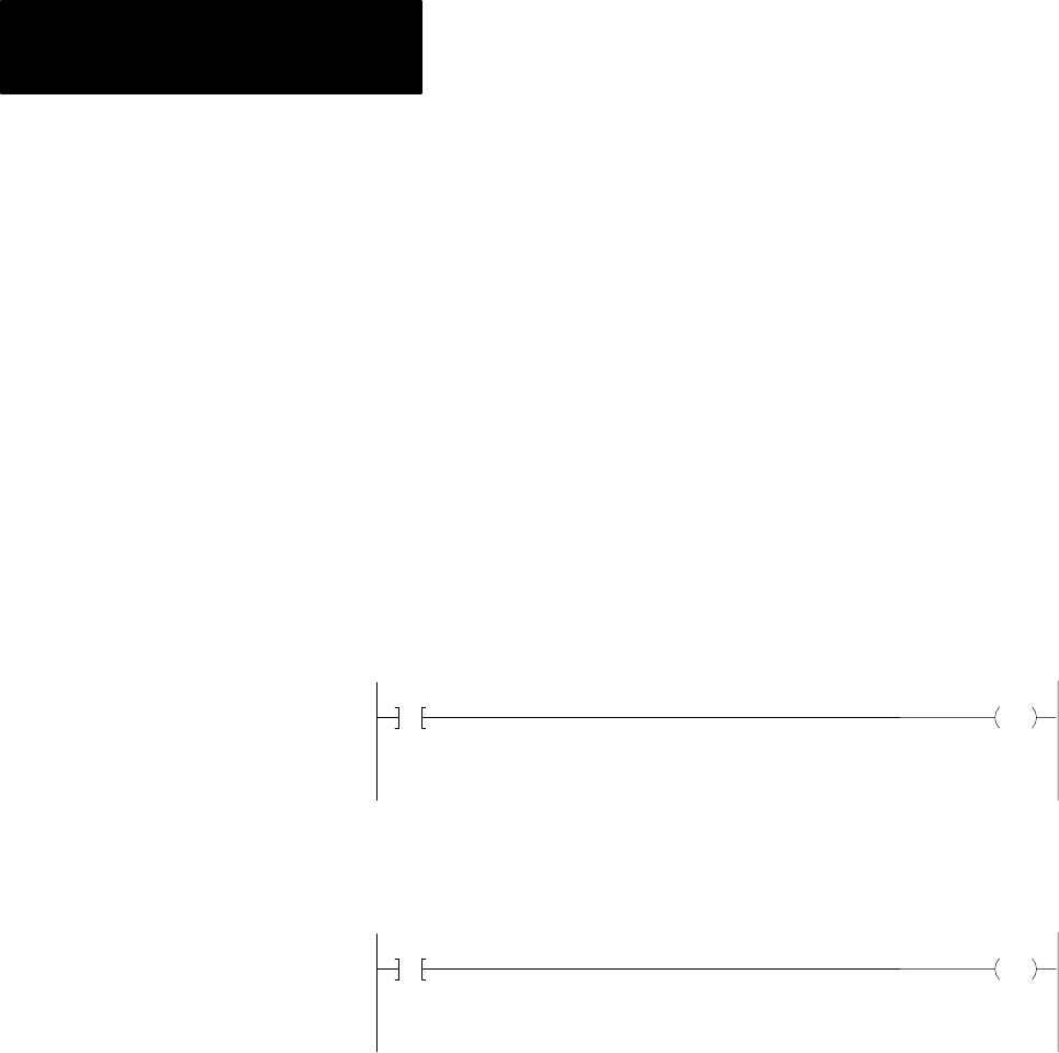
The Output Latch –(L)– instruction tells the processor to latch and set a
specified data table bit when the rung is true. It is usually paired with an
unlatch instruction.
113
04
L
010
00
Bit Controlling
Output Latch
The Output Unlatch –(U)– instruction tells the processor to unlatch and
reset a specific data table bit. It is usually paired with a latch instruction.
113
05
U
010
00
Bit Controlling
Output Unlatch
Important: The conditions for the Output Unlatch instruction must be
different from the conditions that precede the Output Latch instruction.
These are retentive instructions. Retentive means that when the rung
condition goes false, the latched bit remains set and the unlatched bit
remains reset until changed by the program.
These instructions control a specific bit based on the rung condition.
When its rung conditions are:
True - Output Latch sets a specified bit.
True - Output Unlatch resets a specified bit.
False - No action is taken.
Output Latch/Unlatch