
User Manual Owner's manual
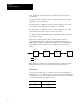
Table Of Contents
- 1772-6.5.8, Mini-PLC-2/02, -2/16, -2/17 Processor, User Manual
- Important User Information
- Summary of Changes
- Table of Contents
- 1 - Using This Manual
- 2 - Fundamentals of a Programmable Controller
- 3 - Hardware Features
- 4 - Installing Your Programmable Controller
- 5 - Starting Your Processor
- 6 - Maintaining and Troubleshooting Your Processor
- 7 - Memory Organization
- 8 - Scan Theory
- 9 - Relay-Like Instructions
- 10 - Program Control Instructions
- 11 - Timers and Counters
- 12 - Data Manipulation and Compare Instructions
- 13 - Three-Digit Math Instructions
- 14 - EAF Math Instructions
- 15 - EAF Log, Trig, and FIFO Instructions
- 16 - EAF Process Control Instructions
- 17 - Jump Instructions and Subroutines
- 18 - Block Transfer
- 19 - Data Transfer Instructions
- 20 - Bit Shift Registers
- 21 - Sequencers
- 22 - Selectable Timer Interrupts
- 23 - Report Generation
- 24 - Program Editing
- 25 - Programming Techniques
- 26 - Program Troubleshooting
- A - Specifications
- B - Processor Comparison Chart
- C - Number Systems
- D - Glossary
- E - Quick Reference
- Index
- Back Cover

RelayLike Instructions
Chapter 9
9-3
Addresses
The processor scans the status of inputs and controls output devices. It
does not go to the input or output terminals to see if outputs are on or off.
Rather, it checks the status of the input and output devices by scanning
corresponding bits in the input and output image area of the data table.
The processor uses addresses to refer to words and bits in the data table.
For addressing purposes, I/O modules in a given I/O rack are organized
into “module groups.” Thus, the module group number of an individual
I/O module depends only on the I/O slot the module occupies. The first
module group in any I/O chassis is always module group 0. Module groups
can be easily identified by module group labels on the latches on top of the
I/O chassis.
Each input and output bit has a five-digit address. If you need a bit address
with more than 5 digits, use the EXPAND ADDR key. Press this key and
then enter the address.
Word addresses, unlike bit address, do not require the EXPAND ADDR
key. Instead, use leading zeros when necessary.
Any time a digit you are entering is not within the proper limits, the
message
DIGIT OUT OF RANGE is displayed. The cursor remains in the
same position until you enter a valid digit.
You can use seven programming instructions to write a program. These
instructions are divided into three categories: bit examining, bit
controlling, and branch instructions.
These instructions examine the status of bits in any data table area except
processor work areas. When an examine on or examine off instruction is
given an address in the I/O image table, the instruction can indirectly
examine the status of a corresponding I/O device. If the image table bit is
on, the condition is true. The I/O device and the I/O image table bit have
the same address.
Bit Examining