
User Manual Owner's manual
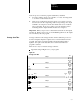
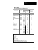
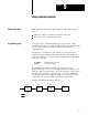
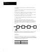
Table Of Contents
- 1772-6.5.8, Mini-PLC-2/02, -2/16, -2/17 Processor, User Manual
- Important User Information
- Summary of Changes
- Table of Contents
- 1 - Using This Manual
- 2 - Fundamentals of a Programmable Controller
- 3 - Hardware Features
- 4 - Installing Your Programmable Controller
- 5 - Starting Your Processor
- 6 - Maintaining and Troubleshooting Your Processor
- 7 - Memory Organization
- 8 - Scan Theory
- 9 - Relay-Like Instructions
- 10 - Program Control Instructions
- 11 - Timers and Counters
- 12 - Data Manipulation and Compare Instructions
- 13 - Three-Digit Math Instructions
- 14 - EAF Math Instructions
- 15 - EAF Log, Trig, and FIFO Instructions
- 16 - EAF Process Control Instructions
- 17 - Jump Instructions and Subroutines
- 18 - Block Transfer
- 19 - Data Transfer Instructions
- 20 - Bit Shift Registers
- 21 - Sequencers
- 22 - Selectable Timer Interrupts
- 23 - Report Generation
- 24 - Program Editing
- 25 - Programming Techniques
- 26 - Program Troubleshooting
- A - Specifications
- B - Processor Comparison Chart
- C - Number Systems
- D - Glossary
- E - Quick Reference
- Index
- Back Cover

Scan Theory
Chapter 8
8-8
Here is an explanation of the rungs in Figure 8.2:
Rung 1 - The count increments its accumulated value each time this rung
is true.
Rung 2 - This rung enables the counter to increment on the next scan. If
we did not have this rung, the counter would always be true and it would
not increment. Remember: Counters increment only on false to
true transitions.
Rung 3 - The timer times in tenths of seconds when we are counting. This
value is displayed on the industrial terminal screen.
Rung 4 - The average scan time is displayed beneath store 2 and store 3
in milliseconds. Replace store 1 using Editing a Get Instruction in a
Completed Rung, chapter 12. Replace store 2 and store 3 instructions.
Refer to three-digit math in chapter 13.
Rung 5 - The counter overflow bit is re-setting the timer.
Rung 6 - The counter overflow bit is resetting the counter.