
User Manual Owner's manual
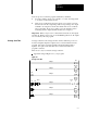
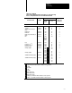
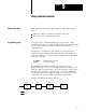
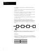
Table Of Contents
- 1772-6.5.8, Mini-PLC-2/02, -2/16, -2/17 Processor, User Manual
- Important User Information
- Summary of Changes
- Table of Contents
- 1 - Using This Manual
- 2 - Fundamentals of a Programmable Controller
- 3 - Hardware Features
- 4 - Installing Your Programmable Controller
- 5 - Starting Your Processor
- 6 - Maintaining and Troubleshooting Your Processor
- 7 - Memory Organization
- 8 - Scan Theory
- 9 - Relay-Like Instructions
- 10 - Program Control Instructions
- 11 - Timers and Counters
- 12 - Data Manipulation and Compare Instructions
- 13 - Three-Digit Math Instructions
- 14 - EAF Math Instructions
- 15 - EAF Log, Trig, and FIFO Instructions
- 16 - EAF Process Control Instructions
- 17 - Jump Instructions and Subroutines
- 18 - Block Transfer
- 19 - Data Transfer Instructions
- 20 - Bit Shift Registers
- 21 - Sequencers
- 22 - Selectable Timer Interrupts
- 23 - Report Generation
- 24 - Program Editing
- 25 - Programming Techniques
- 26 - Program Troubleshooting
- A - Specifications
- B - Processor Comparison Chart
- C - Number Systems
- D - Glossary
- E - Quick Reference
- Index
- Back Cover
Scan Theory
Chapter 8
8-3
Next, the processor scans the program statement by statement:
1. For each condition, the processor checks, or “reads,” the image table
to see if the condition has been met.
2. If the set of conditions has been met, the processor writes a one into
the bit location in the output image table corresponding to the output
terminal to be energized. On the other hand, if the set of conditions
has not been met, the processor writes a zero into that bit location,
indicating that the output terminal should not be energized.
Important: When your processor is in the Remote Test mode, all outputs
are held off. When your processor is in the Run/Program mode, all outputs
are controlled by the user program.
Average scan time is the average amount of time it takes the processor to
monitor and update input and outputs, and to execute instructions in the
program. The scan is performed serially; first the I/O image table is
updated, other parts of the data table are not scanned, then the user
program is scanned.
There are two ways to measure average scan time:
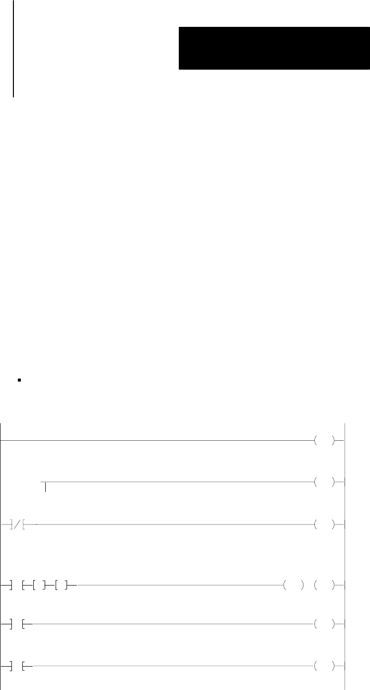
Append the rungs in Figure 8.2 to your program.
Figure 8.2
Average
Scan T
ime
031
14
CTU
031
PR 999
031
14
CTU
031
PR 999
RTO
032
0.1
032
000
Store
010
GG
:
Store
000
AC 000
AC 000
PR 999
AC 000
1
031
14
RTR
032
PR 999
:
Store
000 .
23
AC 000
031
14
RTR
032
PR 999
AC 000
Rung 1
Rung 2
Rung 3
Rung 4
Rung 5
Rung 6
Average Scan Time