
User Manual Owner's manual
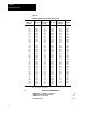
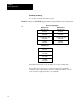
Table Of Contents
- 1772-6.5.8, Mini-PLC-2/02, -2/16, -2/17 Processor, User Manual
- Important User Information
- Summary of Changes
- Table of Contents
- 1 - Using This Manual
- 2 - Fundamentals of a Programmable Controller
- 3 - Hardware Features
- 4 - Installing Your Programmable Controller
- 5 - Starting Your Processor
- 6 - Maintaining and Troubleshooting Your Processor
- 7 - Memory Organization
- 8 - Scan Theory
- 9 - Relay-Like Instructions
- 10 - Program Control Instructions
- 11 - Timers and Counters
- 12 - Data Manipulation and Compare Instructions
- 13 - Three-Digit Math Instructions
- 14 - EAF Math Instructions
- 15 - EAF Log, Trig, and FIFO Instructions
- 16 - EAF Process Control Instructions
- 17 - Jump Instructions and Subroutines
- 18 - Block Transfer
- 19 - Data Transfer Instructions
- 20 - Bit Shift Registers
- 21 - Sequencers
- 22 - Selectable Timer Interrupts
- 23 - Report Generation
- 24 - Program Editing
- 25 - Programming Techniques
- 26 - Program Troubleshooting
- A - Specifications
- B - Processor Comparison Chart
- C - Number Systems
- D - Glossary
- E - Quick Reference
- Index
- Back Cover
Scan Theory
Chapter 8
8-2
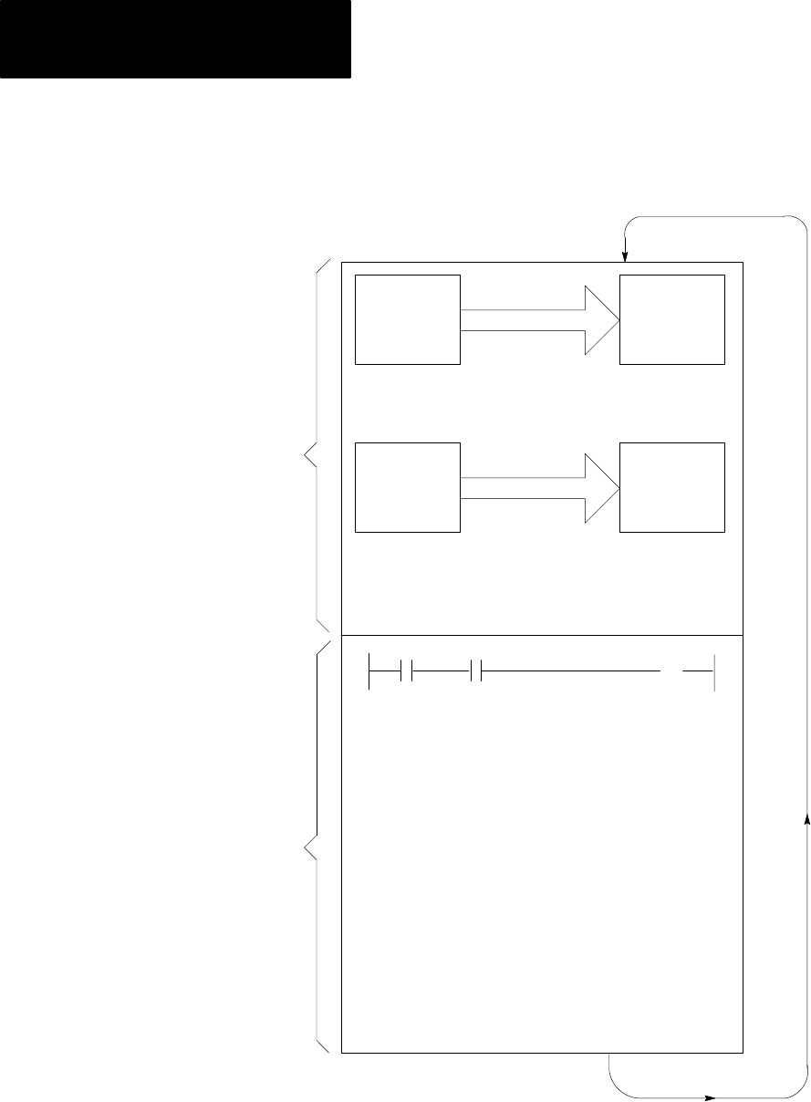
Figure 8.1
The
Processor Scans W
ith This Sequence
10351-I
Output
Image
Table
Input
Terminals
Input
Image
Table
Output
Terminals
Copy output image table status
into output terminal circuits.
Copy input terminal status into
input image table
Program Statement
Execute each program rung in
sequence, writing into bits in the
data table, including the output
image table.
( )
I/O
Scan
Program
Scan
Upon power-up, the processor begins the scan sequence with a program
pre-scan. The processor then proceeds with the I/O scan. Data from output
image table is written to the output modules. Data from the input modules
is read into the input image table.