
User Manual Owner's manual
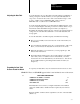
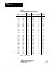
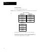
Table Of Contents
- 1772-6.5.8, Mini-PLC-2/02, -2/16, -2/17 Processor, User Manual
- Important User Information
- Summary of Changes
- Table of Contents
- 1 - Using This Manual
- 2 - Fundamentals of a Programmable Controller
- 3 - Hardware Features
- 4 - Installing Your Programmable Controller
- 5 - Starting Your Processor
- 6 - Maintaining and Troubleshooting Your Processor
- 7 - Memory Organization
- 8 - Scan Theory
- 9 - Relay-Like Instructions
- 10 - Program Control Instructions
- 11 - Timers and Counters
- 12 - Data Manipulation and Compare Instructions
- 13 - Three-Digit Math Instructions
- 14 - EAF Math Instructions
- 15 - EAF Log, Trig, and FIFO Instructions
- 16 - EAF Process Control Instructions
- 17 - Jump Instructions and Subroutines
- 18 - Block Transfer
- 19 - Data Transfer Instructions
- 20 - Bit Shift Registers
- 21 - Sequencers
- 22 - Selectable Timer Interrupts
- 23 - Report Generation
- 24 - Program Editing
- 25 - Programming Techniques
- 26 - Program Troubleshooting
- A - Specifications
- B - Processor Comparison Chart
- C - Number Systems
- D - Glossary
- E - Quick Reference
- Index
- Back Cover
Memory Organization
Chapter 7
7-12
Examining the Memory
If you want to examine the memory layout:
SEARCH The word SEARCH appears in the lower left hand corner of the screen.
54
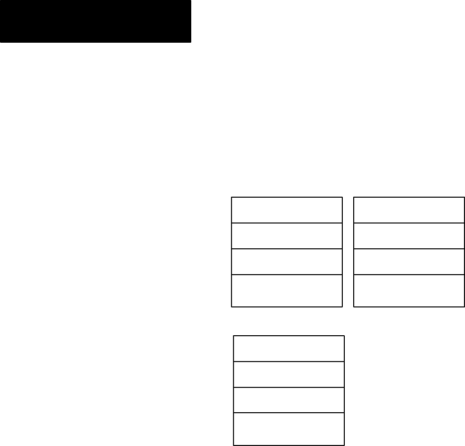
Memory Layout Display
MiniPLC2/16
MiniPLC2/17
Data
T
able Size
128 words
User Program Area
0001 words
User Message Area
0000 words
Unused Memory
Available
3967 words
Data T
able Size
128 words
User Program Area
0001 words
User Message Area
0000 words
Unused Memory
Available
7807 words
MiniPLC2/02
Data T
able Size
128 words
User Program Area
0001 words
User Message Area
0000 words
Unused Memory
Available
1919 words
This illustrates the memory layout display for a 128 word data table.
Even if there are no messages or programs in the memory, the END
statement is there and it requires one word. Adding the number of words
in the four areas equals the memory size (decimal).