
User Manual Owner's manual
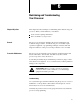
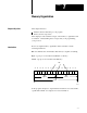
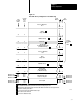
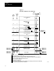
Table Of Contents
- 1772-6.5.8, Mini-PLC-2/02, -2/16, -2/17 Processor, User Manual
- Important User Information
- Summary of Changes
- Table of Contents
- 1 - Using This Manual
- 2 - Fundamentals of a Programmable Controller
- 3 - Hardware Features
- 4 - Installing Your Programmable Controller
- 5 - Starting Your Processor
- 6 - Maintaining and Troubleshooting Your Processor
- 7 - Memory Organization
- 8 - Scan Theory
- 9 - Relay-Like Instructions
- 10 - Program Control Instructions
- 11 - Timers and Counters
- 12 - Data Manipulation and Compare Instructions
- 13 - Three-Digit Math Instructions
- 14 - EAF Math Instructions
- 15 - EAF Log, Trig, and FIFO Instructions
- 16 - EAF Process Control Instructions
- 17 - Jump Instructions and Subroutines
- 18 - Block Transfer
- 19 - Data Transfer Instructions
- 20 - Bit Shift Registers
- 21 - Sequencers
- 22 - Selectable Timer Interrupts
- 23 - Report Generation
- 24 - Program Editing
- 25 - Programming Techniques
- 26 - Program Troubleshooting
- A - Specifications
- B - Processor Comparison Chart
- C - Number Systems
- D - Glossary
- E - Quick Reference
- Index
- Back Cover
Memory Organization
Chapter 7
7-4
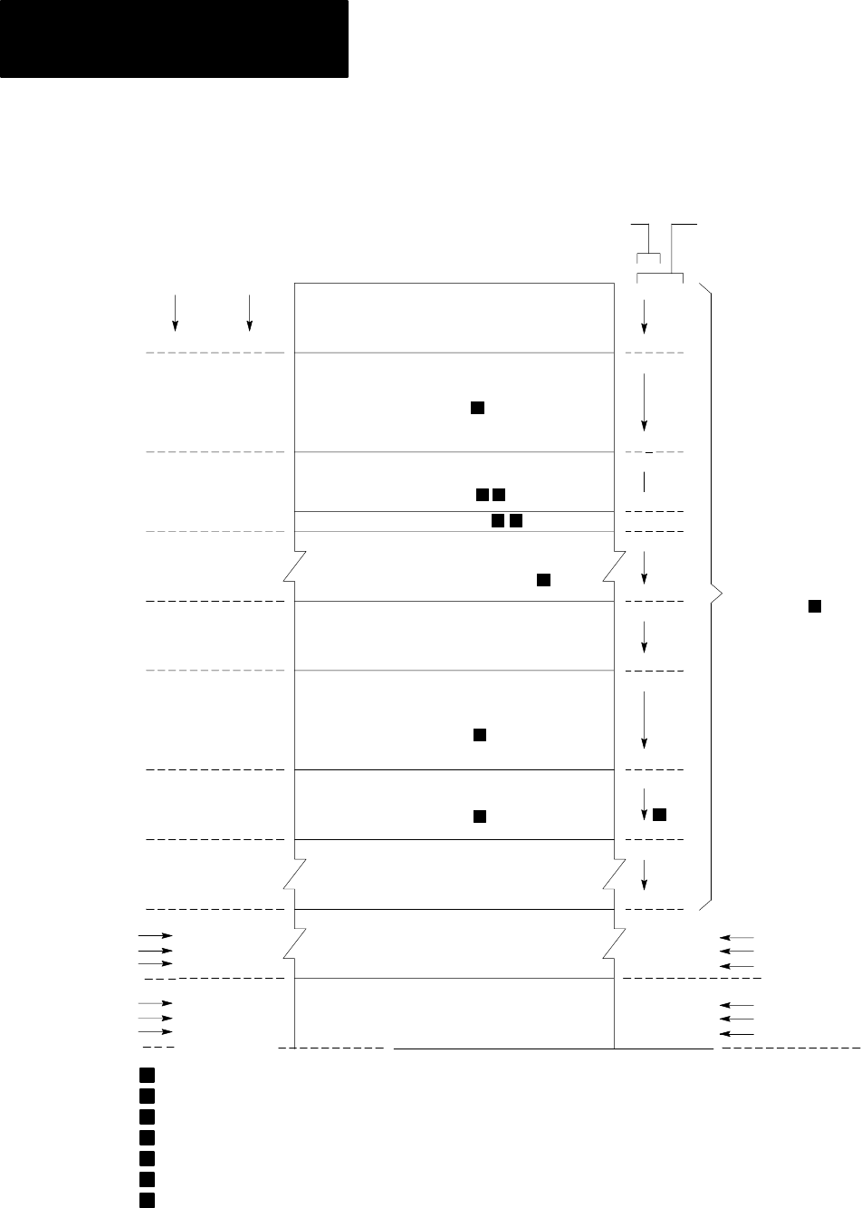
Figure 7.3
Data Table Configured for 1Slot Addressing
Processor Work Area
Output Image Table
Rack 1
Reserved
Timer Counter
Accumulated Values (AC)
(or Bit Word Storage)
Processor Work Area
No. 2
Timer Counter
Preset Values (PR)
(or Bit Word Storage)
Expanded Data Table
and/or User Program
Total
Decimal
Words
8
16
24
64
72
88
128
80
8
8
8
40
8
8
40
8
Word
Bit
000
007
010
017
020
026
027
030
077
100
107
110
117
120
127
130
177
200
00
17
00
17
00
17
00
17
00
17
00
17
00
17
00
17
00
1
2
3
4
User Program
1920 1792
2048 128
3968
7808
3840
7680
4096
7936
128
128
MiniPLC2/02
MiniPLC2/16
MiniPLC2/17
MiniPLC2/02
MiniPLC2/16
MiniPLC2/17
3577 17
3777 17
7577
17177
17
17
7777
17377
17
17
MiniPLC2/02
MiniPLC2/16
MiniPLC2/17
MiniPLC2/02
MiniPLC2/16
MiniPLC2/17
6
6
Output Image Table
Rack 2
1
7
Input Image Table
Rack 1
6
Input Image Table
Rack 2
Configured for
1Slot Addressing
Data Table
5
10349–I
Decimal
Words
Per
Area
Address
Address
No. 1
May not be used for accumulated values.
Not available for bit/word storage. Bits in this word are used by the processor.
Unused timer/counter memory words can reduce data table size and increase user program area.
Do not use word 127 for block transfer data storage.
Can be decreased to 48 words.
1
2
3
4
5
Used with 1slot addressing.6
You cannot put an output or block transfer module in rack 2, I/O group 7 when using 1slot addressing.7
You can put an input module in rack 2, I/O group 7.