
User Manual Owner's manual
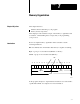
Table Of Contents
- 1772-6.5.8, Mini-PLC-2/02, -2/16, -2/17 Processor, User Manual
- Important User Information
- Summary of Changes
- Table of Contents
- 1 - Using This Manual
- 2 - Fundamentals of a Programmable Controller
- 3 - Hardware Features
- 4 - Installing Your Programmable Controller
- 5 - Starting Your Processor
- 6 - Maintaining and Troubleshooting Your Processor
- 7 - Memory Organization
- 8 - Scan Theory
- 9 - Relay-Like Instructions
- 10 - Program Control Instructions
- 11 - Timers and Counters
- 12 - Data Manipulation and Compare Instructions
- 13 - Three-Digit Math Instructions
- 14 - EAF Math Instructions
- 15 - EAF Log, Trig, and FIFO Instructions
- 16 - EAF Process Control Instructions
- 17 - Jump Instructions and Subroutines
- 18 - Block Transfer
- 19 - Data Transfer Instructions
- 20 - Bit Shift Registers
- 21 - Sequencers
- 22 - Selectable Timer Interrupts
- 23 - Report Generation
- 24 - Program Editing
- 25 - Programming Techniques
- 26 - Program Troubleshooting
- A - Specifications
- B - Processor Comparison Chart
- C - Number Systems
- D - Glossary
- E - Quick Reference
- Index
- Back Cover
Chapter
7
7-1
Memory Organization
This chapter discusses:
hardware and its relationship to your program
memory and its components
This chapter provides detailed concepts of the memory’s organization and
its structure. Understanding these concepts aids you in programming
your processor.
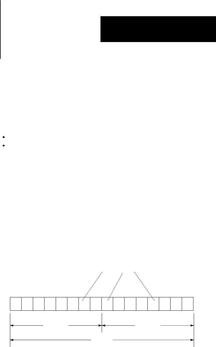
Before we explain memory organization and its structure, read the
following definitions:
Bit - the smallest unit of information that memory is capable of retaining
Byte - a group of 8 consecutive bits (00-07
08
or 10-17
08
)
Word - a group of 16 consecutive bits (00-17
08
)
10346-I
17 16 15 14 13 12 11 10 07 06 05 04 03 02 01 00
Byte
(upper)
Byte
(lower)
Word
Bits
In the program, the input or output instruction address is associated with a
specific I/O terminal. See chapter 5 for more information.
Chapter Objectives
Introduction