
User Manual Owner's manual
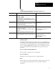
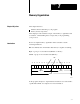
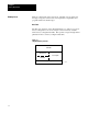
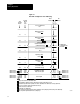
Table Of Contents
- 1772-6.5.8, Mini-PLC-2/02, -2/16, -2/17 Processor, User Manual
- Important User Information
- Summary of Changes
- Table of Contents
- 1 - Using This Manual
- 2 - Fundamentals of a Programmable Controller
- 3 - Hardware Features
- 4 - Installing Your Programmable Controller
- 5 - Starting Your Processor
- 6 - Maintaining and Troubleshooting Your Processor
- 7 - Memory Organization
- 8 - Scan Theory
- 9 - Relay-Like Instructions
- 10 - Program Control Instructions
- 11 - Timers and Counters
- 12 - Data Manipulation and Compare Instructions
- 13 - Three-Digit Math Instructions
- 14 - EAF Math Instructions
- 15 - EAF Log, Trig, and FIFO Instructions
- 16 - EAF Process Control Instructions
- 17 - Jump Instructions and Subroutines
- 18 - Block Transfer
- 19 - Data Transfer Instructions
- 20 - Bit Shift Registers
- 21 - Sequencers
- 22 - Selectable Timer Interrupts
- 23 - Report Generation
- 24 - Program Editing
- 25 - Programming Techniques
- 26 - Program Troubleshooting
- A - Specifications
- B - Processor Comparison Chart
- C - Number Systems
- D - Glossary
- E - Quick Reference
- Index
- Back Cover

Starting Your Processor
Chapter 5
5-19
Using Pushbuttons
ATTENTION: Use only trained personnel to conduct this test.
Have a trained person at appropriate emergency stop switches to
de-energize output devices that could cause hazardous
operation.
To use a pushbutton to test your output devices, do the following:
1. Connect a normally-open/momentary-close pushbutton switch as an
input device to an input module.
2. Connect the industrial terminal to your processor. (See chapter 4.)
3. Select the RUN mode of operation.
4. Use an examine-on address corresponding to the address of the
pushbutton. Use an energize address corresponding to the output
device being tested. For example, enter a rung similar to this one:
111
14
014
00
ATTENTION: Test only one rung at a time. Do not program
multiple rungs; unpredictable machine operation can occur.
5. Close the pushbutton switch and see if the input and output address
instructions are intensified
6. If the output instruction is not intensified, verify your test setup and
the input address.
7. Make sure that the output module’s status indicator lights. If the
indicator lights, repeat the setup procedure for another output device.
8. If the indicator does not light, check the following:
power source for the output device
I/O chassis power supply
connections to the field wiring arm
address of the output I/O module (rack, group, slot, terminal)
examine-on address of the pushbutton switch