
User Manual, AUX FUNCT PROM Manual

Programming
Chapter 3
333
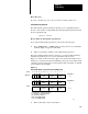
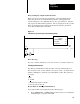
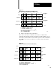
Figure 3.27
General
AF4 Log to Base 10 Function W
ord and Digit Format
171615141312111076543210
Digit 1
(MSD)
Digit 2
Bit No.
Data Address
m
Digit 2
Operand
Digit 5
Result Address
n
Result
DE
n + 1
E = Enable Bit (1 = Function in Progress)
D = Done Bit (1 = Function Complete)
MSD = Most Significant Digit
LSD = Least Significant Digit
11499
Digit 3
(LSD)
Digit 3
Digit 1
(MSD)
Digit 4
Digit 6
(LSD)
ER = Error Bit (1 = Input is 0)
ER
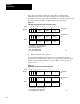
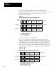
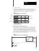
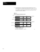
3. Enter a data address and a result address.
If we select a data address of 201 and a result address of 305, the AF4
establishes the data table format shown in Figure 3.28. The data address is
reserved for the three digits of the number whose log you want. The result
address, 305, is reserved for the first three digits of the resultant log; the next
higher address, 306, is reserved for the last three digits. The implied decimal
point in the result is after the MSD.
Figure 3.28
AF4
Log to Base 10 Function Format After Address Entry
171615141312111076543210
Digit 1
(MSD)
Digit 2
Bit No.
Data Address
Digit 2
Operand
Digit 5
Result Address
Result
DE
E = Enable Bit (1 = Function in Progress)
D = Done Bit (1 = Function Complete)
MSD = Most Significant Digit
LSD = Least Significant Digit
11500
Digit 3
(LSD)
Digit 3
Digit 1
(MSD)
Digit 4
Digit 6
(LSD)
ER = Error Bit (1 = Input is 0)
ER
201
305
306