
User Manual, AUX FUNCT PROM Manual

Programming
Chapter 3
323
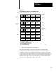
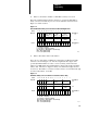
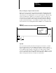
Figure 3.14
General
AF4 Division Function W
ord and Digit Format
17161514131211107 6 5 4 3 2 1 0
S
Digit 1
(MSD)
Digit 2 Digit 3
Bit No.
Data Address
m
Digit 5
Digit 6
Digit 4
(LSD)
Operand 1
S
Digit 1
(MSD)
Digit 2 Digit 3
Digit 5
Digit 6
Digit 4
(LSD)
Operand 2
S
Digit 1
(MSD)
Digit 2 Digit 3
Result Address
n
Digit 5Digit 4
Result
DE
m + 1
m + 2
m + 3
n + 1
E = Enable Bit (1 = Function in Progress)
S = Sign Bit (1= Negative)
D = Done Bit (1 = Function Complete)
MSD = Most Significant Digit
LSD = Least Significant Digit
11490
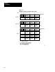
Digit 8 Digit 9
Digit 11
Digit 12
Digit 10
(LSD)
Digit 6
Digit 7
n + 2
n + 3
ER
ER = Illegal Operand (Divide by Zero)
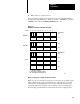
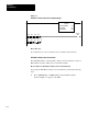
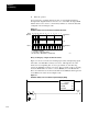
3. Enter a data address and a result address.
If we enter a data address of 201 and a result address of 305, the AF4
establishes the data table format shown in Figure 3.15. The data address
eventually contains the most significant three digits of operand 1. The AF4
reserves the next three higher addresses for the least significant three digits of
operand 1 and the six digits of operand 2. The result address contains the most
significant three digits of the result. The AF4 reserves the next three higher
addresses for the remaining nine digits of the result.