
User Manual, AUX FUNCT PROM Manual

Programming
Chapter 3
312
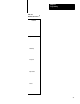
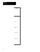
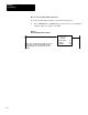
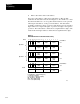
3. Enter a data address and a result address.
If we select a data address of 201 and a result address of 305, the AF4
establishes the data table format shown in Figure 3.3. Be careful not to select
data and result addresses so close together that the addresses of the operands
following the data address overlap your result address. The data address
eventually contains three digits of operand 1. The AF4 reserves the next three
higher addresses for digits 4 through 6 of operand 1 and digits 1 through 6 of
operand 2. The result address contains the most significant three digits of the
result and the next higher address contains the least significant three digits.
Figure 3.3
AF4
Addition Function Formal After Address Entry
171615141312111076543210
S
Digit 1
(MSD)
Digit 2 Digit 3
Bit No.
Data Address
Digit 5
Digit 6
Digit 4
(LSD)
Operand 1
S
Digit 1
(MSD)
Digit 2 Digit 3
Digit 5
Digit 6
Digit 4
(LSD)
Operand 2
S
Digit 1
(MSD)
Digit 2 Digit 3
Result Address
Digit 5
Digit 6
Digit 4
(LSD)
Result
DERE
E = Enable Bit (1 = Function in Progress)
S = Sign Bit (1= Negative)
D = Done Bit (1 = Function Complete)
ER = Error Bit (1 = Overflow)
MSD = Most Significant Digit
LSD = Least Significant Digit
11482
201
202
203
204
305
306