Auxiliary Function PROM (Cat. No.
Table of Contents Introduction . . . . . . . . . . . . . . . . . . . . . . . . . . . . . . . . . . . . 1 1 General . . . . . . . . . . . . . . . . . . . . . . . . . . . . . . . . . . . . . . . . . . . Functions . . . . . . . . . . . . . . . . . . . . . . . . . . . . . . . . . . . . . . . . . Applications . . . . . . . . . . . . . . . . . . . . . . . . . . . . . . . . . . . . . . . . Manual's Purpose . . . . . . . . . . . . . . . . . . . . . . . . . . . . . . . . . . . Audience . . . . . . . . . . . . . .
Chapter 1 Introduction General Installation of the Auxiliary Function (AF) PROM (cat. no. 1772-AF4 in your Mini-PLC-2/15 controller lets you expand its mathematical capabilities. For simplification, throughout this manual we refer to the Auxiliary Function PROM (cat. no. 1772-AF4) as the AF4. The AF4 can only be used with the series A Mini-PLC-2/15 processor module, firmware revision 11 or later (cat. no. 1772-LV).
Chapter 1 Introduction Functions The AF4 performs the following arithmetic functions: Six digit add and subtract Six digit multiply and divide BCD to binary conversion Binary to BCD conversion Logarithm of a three digit number to the base 10 Logarithm of a three digit number to the base 3 Exponential function -e+X Power function -y+X Reciprocal of a number - 1 +X Sine of an angle - sin X Cosine of an angle - cos X Square root of a number -x 0.
Chapter 2 Installation General During AF4 installation, take special care not to bend or contaminate the pins. Bent or dirty pins can prevent proper AF4 programming and use. The AF4’s transparent window is covered with the product label to avoid accidental alteration of memory from UV light sources. Do not remove this label. Store the AF4 in its shipping container when not installed in a Mini-PLC-2/15 processor.
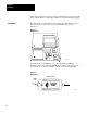
Chapter 2 Installation When these precautions are followed, the potential difference between the AF4 pins is reduced thereby reducing the problems associated with static discharges. Installation The AF4 fits into a 28-pin ZIF (zero insertion force) socket, which is located under a hinged door at the lower side of the Mini-PLC-2/15 processor (Figure 2.1). Figure 2.1 PROM Socket 10715 I On the underside of the PROM door is a label that illustrates PROM installation.
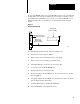
Chapter 2 To access the PROM socket, remove the Mini-PLC-2/15 processor module from the I/O chassis. If you desire to maintain processor memory contents, connect an external battery pack (Figure 2.3) to the processor with the Mini-Processor Transport Cable (cat. no. 1772-CD) prior to removing the module from the chassis. Figure 2.3 External Battery Backup Battery Pack (Cat. No. 1771 BB) Mini PLC 2/15 Processor (Cat. No. 1772 LV) Mini Processor Transport Cable (Cat. No.
Chapter 2 Installation Removal 2 4 To remove the AF4, perform the following steps: 1. Turn the mode select switch to PROG. 2. To maintain processor memory contents connect an external battery pack to the processor with the mini-processor transport cable (Figure 2.3). 3. Remove AC power from the I/O chassis power supply. 4. Remove the processor module from the I/O chassis. 5. Loosen the screw, lift up the PROM door, and push the ON tab in to unlock the socket (Figure 2.2). 6.
Chapter 3 Programming General You access the AF4 by pressing [SHIFT][EAF] (execute auxiliary function) or [SHIFT][SCT] on the keyboard of your Industrial Terminal (cat. no. 1770-T3). The instruction is an output instruction and may be preceded on a rung by condition instructions. Once you enter the function, the block diagram of Figure 3.1 appears on the CRT. To program a specific mathematics functions, you would enter the appropriate function number (Table 3.A).
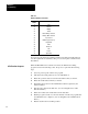
Chapter 3 Programming Table 3.A Function Numbers for the AF4 Function Number Mathematical Operation 01 Add 02 Subtract 03 Multiply 04 Divide 13 BCD to Binary conversion 14 Binary to BCD conversion 30 Log to base 10 31 Natural log (log to base e) 32 Exponential 33 Power 34 Reciprocal 35 Sine 36 Cosine 37 Square Root You enter an existent function number and then enter data and result addresses (we will explain this in detail later).
Chapter 3 Programming AF4 Automatic Checks To guard against improper program execution, automatic check routines are incorporated in the AF4. The processor uses these routines to prevent the following: Executing AF4 functions having invalid function addresses Spending so much time executing AF4 functions that the controller neglects its main program and I/O scans Invalid Function Addresses Valid AF4 function addresses include the I/O image table and the data table (except word 027).
Chapter 3 Programming Avoiding Excessive AF4 Execution Times Table 3.B lists execution times for AF4 functions. To avoid excessive AF4 function execution times, an interlock system is designed into the AF4. This system automatically checks and does the following: Permits no AF4 function to run longer than 6ms without returning processor scan to the processor. During a program scan each true AF4 function rung which can be completed in a single scan will be completed as it is encountered.
Chapter 3 Programming Table 3.
Chapter 3 Programming Function Sine Cosine Square Root (y00.5) BCD to Binary Binary to BCD 3 6 N A W u vo m g rb .
Chapter 3 Programming Function N A W u vo m g rb .se T tr iT o m if em S ec a n s Addition Subtraction Multiplication Division [1]These times are calculated for a single AF4 function. Overhead for AF4 lock maintenance and multiple runs through the ladder program to complete some function is included. Programming Specific Mathematical Functions In this section we explain the following for each of the AF4 functions: What it is How to enter it in your program Its format in the data table a.
Chapter 3 Programming b. digit location Sample entry and display rungs. Although there are several techniques to enter this data, we use get instructions. Error messages. If an AF4 function has special error message responses to specific illegal programming procedures, we state these responses.
Chapter 3 Programming Status Bits The most significant four bits of the most significant word of the result data area are reserved for status bits. These bits have the following meanings: Enable - bit 17 Sign - bit 16 Done - bit 15 Error bit - bit 14 The enable bit is set at the start of an AF4 function and reset upon completion. The sign bit, if set, indicates a negative value. The done bit is reset at the start of an AF4 function and set upon completion.
Chapter 3 Programming How to enter an AF4 Addition Function To program an AF4 addition function, perform the following steps: 1. Press [SHIFT][EAF] or [SHIFT][SCT] on the keyboard of your industrial terminal. Figure 3.1 appears on the CRT Figure 3.1 Execute Auxiliary Function Format Execute Aux Function Numbers shown are default values and must be replaced by your values. The number of default address digits originally displayed, 3 or 4, depends on the size of the data table.
Chapter 3 Programming 2. Enter 01, the function number for AF4 addition. This entry identifies that the function entered is to perform an AF4 addition and that the processor use the data table format shown in Figure 3.2 when executed. Operands 1 and 2 represent the two 6-digit numbers we wish to add. The six digits of operand 1 are represented in BCD by the groups of bits labeled digit 1 through 6. Digit 1 and digit 6 are the most significant and the least significant digits respectively.
Chapter 3 Programming 3. Enter a data address and a result address. If we select a data address of 201 and a result address of 305, the AF4 establishes the data table format shown in Figure 3.3. Be careful not to select data and result addresses so close together that the addresses of the operands following the data address overlap your result address. The data address eventually contains three digits of operand 1.
Chapter 3 Programming 4. Enter values for operands 1 and 2. You can enter these values from the keyboard of your industrial terminal or through ladder diagram functions. Entry of operand 1 - 102746 and operand 2 256384 produces the result 359130 when the addition function executes. Figure 3.4 shows how the result is stored. Figure 3.
Chapter 3 Programming Figure 3.5 AF4 Addition Function Input and Result Display Rungs Execute Aux Function Function Number: Data Addr: Result Addr: 201 G 102 305 G 359 202 G 746 306 G 130 203 G 256 01 201 305 204 G 384 Storage Bit Error Message If the resultant sum has more than six integers, the error bit (bit 14) is set indicating overflow. AF4 Subtraction Function An AF4 subtraction function operates on two 6-digit BCD numbers and presents the result in a third 6-digit BCD number.
Chapter 3 Programming Figure 3.6 General AF4 Subtraction Function Word Digit Format 17 16 15 14 13 12 11 10 Bit No.
Chapter 3 Programming Figure 3.7 AF4 Subtraction Function Format After Address Entry 17 16 15 14 13 12 11 10 Bit No.
Chapter 3 Programming Figure 3.
Chapter 3 Programming Error Message If the result has more than six integers, the error bit (bit 14) is set indicating overflow. AF4 Multiplication Function An AF4 multiplication function operates on two 6-digit BCD numbers and presents the results in a 12-digit BCD number. (+xxx xxx.) x (+xxx xxx.) = +xxx xxx xxx xxx. How to Enter an AF4 Multiplication Function To program an AF4 multiplication function, perform the following steps: 1.
Chapter 3 Programming Figure 3.10 General AF4 Multiplication Function Word and Digit Format Bit No.
Chapter 3 Programming Figure 3.11 AF4 Multiplication Function format After Address Entry Bit No.
Chapter 3 Programming 4. Enter values for operands 1 and 2. You can enter these values from the keyboard of your industrial terminal or through ladder diagram functions. Entry of operand 1 - 000400 and operand 2 000200 produces the result 00000080000 (Figure 3.12). Figure 3.12 AF4 Multiplication Function Format After Execution Bit No.
Chapter 3 Programming Figure 3.13 Af4 Multiplication Function Input and Result Display Rungs Execute Aux Function Function Number: Data Addr: Result Addr: 201 G 000 305 G 153 202 G 400 306 G 638 203 G 000 306 G 638 03 201 305 204 G 200 306 G 638 Storage Bit AF4 Division Function An AF4 division function operates on two 6-digit BCD numbers and presents the results in a 12-digit BCD number. (+xxx xxx.) : (+xxx xxx.) = +xxx xxx.
Chapter 3 Programming Figure 3.14 General AF4 Division Function Word and Digit Format Bit No.
Chapter 3 Programming Figure 3.15 AF4 Division Function Format After Address Entry Bit No.
Chapter 3 Programming 4. Enter values for operands 1 and 2. You can enter these numbers from the keyboard of your industrial terminal or through ladder diagram functions. Entry of operand 1 = 000400 and operand 2 - 000200 produces the result 000002.000000 (Figure 3.16). Figure 3.16 AF4 Division Function Format After Execution Bit No.
Chapter 3 Programming Figure 3.17 AF4 Division Function Input and Result Display Rungs Execute Aux Function Function Number: Data Addr: Result Addr: 201 G 000 305 G 000 202 G 400 306 G 002 203 G 000 306 G 000 04 201 305 204 G 200 306 G 000 Storage Bit Error Message If you divide by zero, the error bit (bit 14) is set and the result reads zero.
Chapter 3 Programming 2. Enter 13, the function number for AF4 BCD to binary conversion. This entry identifies that the function entered is to perform an AF4 BCD to binary conversion and that the processor use the data table format shown in Figure 3.18 when executed. Figure 3.18 General AF4 BCD to Binary Conversion Function Word and Digit Format Bit No.
Chapter 3 Programming 4. Enter the operand. You can enter the operand from the keyboard of your industrial terminal or through ladder diagram functions. If we choose to enter 4095, the largest BCD number that we can convert to a 12 bit binary number, we obtain the data table configuration shown in Figure 3.20. Figure 3.20 Af4 BCD to Binary Conversion Function Format After Execution Bit No.
Chapter 3 Programming Error Message If you enter a BCD number larger than 4095, the error bit (bit 14) is set and the result reads zero. AF4 Binary to BCD Conversion Function The AF4 binary to BCD conversion function converts a 12-bit binary number to a BCD number (from 0 to 4095). How to Enter an AF4 Binary to BCD Conversion Function To program an AF4 binary to BCD conversion function, perform the following steps: 1. Press [SHIFT][EAF]or [SHIFT][SCT] on the keyboard of your industrial terminal. Figure 3.
Chapter 3 Programming Figure 3.23 AF4 Binary to BCD Conversion Function Format After Address Entry Bit No. 17 16 15 14 13 12 11 10 Operand Result S 6 5 4 3 2 1 0 Data Address 200 12 Bit Binary Number S E 7 D Digit 1 (MSD) (Always = 0) Digit 2 (Always = 0) Digit 3 Result Address 300 Digit 4 Digit 5 Digit 6 (LSD) 301 E = Enable Bit (1 = Function in Progress) S = Sign Bit (1= Negative) D = Done Bit (1 = Function Complete) MSD = Most Significant Digit LSD = Least Significant Digit 4.
Chapter 3 Programming Entry and Display of Input and Result Values Figure 3.25 shows one method for inserting input values and displaying inputs and results of an AF4 binary to BCD conversion function. Although there are other methods for accomplishing this, we chose get instructions. The first rung requests an AF4 binary to BCD conversion function. The top branch of the second rung shows the binary number (in the hexadecimal notation FFF) that we want converted to BCD.
Chapter 3 Programming Figure 3.26 Transfer of Sign Bit 200 G 201 PUT 200 201 PUT 16 15 Execute Aux Function Function Number: Data Addr: Result Addr: 14 201 AF4 Log to Base 10 Function The AF4 log to the base 10 function finds the log of a 3-digit BCD integer. The result is a 6-digit BCD number with an implied decimal point after the most significant digit. log (xxx.) - x.xx xxx How to Enter an AF4 Log to Base 10 Function To program an AF4 log to base 10 function perform the following steps: 1.
Chapter 3 Programming Figure 3.27 General AF4 Log to Base 10 Function Word and Digit Format 17 16 15 14 13 12 11 10 Bit No. Operand E D ER 7 6 5 Digit 1 (MSD) Digit 2 Digit 1 (MSD) Digit 2 Digit 4 Digit 5 4 3 2 1 0 Data Address m Digit 3 (LSD) Result Address n Digit 3 Result Digit 6 (LSD) n+1 E = Enable Bit (1 = Function in Progress) D = Done Bit (1 = Function Complete) ER = Error Bit (1 = Input is 0) MSD = Most Significant Digit LSD = Least Significant Digit 3.
Chapter 3 Programming 4. Enter the operand. You can enter the operand from the keyboard of your industrial terminal or through ladder diagram functions. Entry of operand - 648 produces the result 2.81157 when the log function executes. Figure 3.29 shows how the result is stored. Figure 3.29 AF4 Log to Base 10 Function Format After Execution Bit No.
Chapter 3 Programming Error Messages If you try to find the log of zero, the error bit is set and the result is zero. AF4 Natural Log Functions The AF4 natural log function finds the natural log of a 3-digit BCD integer to the base e. The result is a 6-digit BCD value with an implied decimal point after the most significant digit. In (xxx.) - x.xx xxx How to Enter an AF4 Natural Log Function To program an AF4 natural log function, perform the following steps: 1.
Chapter 3 Programming If we enter a data address of 201 and a result address of 305, the AF4 establishes the data table format shown in Figure 3.32. The data address eventually contains the operand. The result address (word 305) contains the first three digits of the result and word 306 contains the last three digits. Figure 3.32 AF4 Natural Log Function Format After Address Entry Bit No.
Chapter 3 Programming Entry and Display of Input and Result Values Figure 3.34 shows one method for inserting the operand and displaying the input value and result of an AF4 natural log function. Although there are several techniques for accomplishing this, we chose get instructions. The first rung requests an AF4 natural log function. The second rung shows the operand 648 in word 201 in the upper branch and the desired natural log 6.47389 in words 305 and 306 in the lower branch. Figure 3.
Chapter 3 Programming 2. Enter 32, the function number for an AF4 exponential function. This entry identifies that the function entered is to perform an AF4 exponential calculation and that the processor use the data table format shown in Figure 3.35 when executed. Figure 3.35 General AF4 Exponential Function Word and Digit Format Bit No.
Chapter 3 Programming 4. Enter the operand. You can enter the operand from the keyboard of your industrial terminal or through ladder diagram functions. Entry of an operand (exponent) of e) of 9.42 yields an exponential function value of 1.23(10)004. The base r resides in word 305 and the exponent of ten resides in word 306 as shown in Figure 3.37. Figure 3.37 AF4 Exponential Function Format After Execution Bit No.
Chapter 3 Programming AF4 Power Function The AF4 power function evaluates y+x and gives the result in terms of a base number r and a power of 10, s, by which you multiply this base number to obtain the power function value. The equation is: y+x = r(10)+s where: y = input base = XXX. x = input exponent = XX.X r = result base = X.XX s = resultant exponent = +XX. (The first digit is always zero) A request for zero to the zero power will result in plus one.
Chapter 3 Programming Figure 3.39 General AF4 Power Function Word and Digit Format Bit No.
Chapter 3 Programming 4. You can enter base y and exponent x values from the keyboard of the industrial terminal or through ladder diagram functions. Entry of y - 124 in word 200 and 2 - 02.0 in word 201 produces the result 15376 when the power function executes. Figure 3.41 shows how the result is stored as 1.53(10)4. The result is truncated. Figure 3.41 AF4 Power Function Format After Execution Bit No.
Chapter 3 Programming Entry and Display of Input and Result Values Figure 3.42 shows one method for inserting the input values and displaying input values and result of an AF4 power function. Although there are several techniques for accomplishing this, we chose get instructions. The first rung requests the AF4 to evaluate a power function. The top branch of the second rung contains the input base, 124, in word 200 and the input exponent 02.0 in word 201. The lower branch of rung 2 contains the result, 1.
Chapter 3 Programming How to Enter an AF4 Reciprocal Function To program an AF4 reciprocal function, perform the following steps: 1. Press [SHIFT][EAF] or [SHIFT][SCT] on the keyboard of your industrial terminal. Figure 3.1 appears on the CRT. 2. Enter 34, the function number for an AF4 reciprocal function. This entry identifies that the function entered is to perform an AF4 reciprocal calculation and that the processor use the data table format shown in Figure 3.43 when executed. Figure 3.
Chapter 3 Programming 3. Enter a data address and a result address. If we choose a data address of 200 and a result address of 305, the AF4 establishes the data table format shown in Figure 3.44. The data address eventually contains the most significant three digits of the operand (the number whose reciprocal we seek). The next higher address, word 201, is reserved for the three least significant digits of the operand.
Chapter 3 Programming Figure 3.45 AF4 Reciprocal Function Format After Execution Bit No. Operand Result 17 16 15 14 13 12 11 10 S (0) E S D ER (0) (0) (0) (0) 7 6 5 4 3 2 1 0 0 0 1 2 4 0 0 8 0 6 4 0 Data Address Result Address E = Enable Bit (1 = Function in Progress) S = Sign Bit (1 = Negative) D = Done Bit (1 = Function Complete) ER = Error Bit (Illegal Operand, 1 = Input is 0) 11513 Entry and Display of Input and Result Values Figure 3.
Chapter 3 Programming AF4 Trigonometric Function Sin xxx. The AF4 sine function finds the sine of a 3-digit BCD angle. The input angle is in degrees. The AF4 presents the result as a 6-digit value with an implied decimal point after the most significant digit. sin xxx. = +x.xx xxx How to Enter an AF4 Sine Function To program an AF4 sine function perform the following steps: 1. Press [SHIFT][EAF] or [SHIFT][SCT} on the keyboard of your industrial terminal. Figure 3.1 appears on the CRT. 2.
Chapter 3 Programming address, word 310, is reserved for the most significant three digits of the sine; the least significant three digits are stored in the next higher address, word 311.
Chapter 3 Programming Figure 3.48 AF4 Sine Function Format After Address Entry Bit No. 17 16 15 14 13 12 11 10 Operand E 7 6 5 S Digit 1 (MSD) Digit 2 S D Digit 1 (MSD) Digit 2 Digit 4 Digit 5 4 3 2 1 0 Data Address 205 Digit 3 (LSD) Result Address 310 Digit 3 Result Digit 6 (LSD) 311 E = Enable Bit (1 = Function in Progress) S = Sign Bit (1 = Negative) D = Done Bit (1 = Function Complete) MSD = Most Significant Digit LSD = Least Significant Digit 4.
Chapter 3 Programming Entry and Display of Input and Result Values Figure 3.50 shows one method for inserting the input angle and displaying the input and the result of an AF4 sine function. Although there are several techniques for accomplishing this, we chose get instructions. The first rung requests the AF4 sine function. The top branch of the second rung shows the angle value 080o in word 205. The lower branch shows the resultant sine 0800 = 0.
Chapter 3 Programming Figure 3.51 General AF4 Cosine Function Word and Digit Format Bit No. 17 16 15 14 13 12 11 10 Operand E 7 6 5 S Digit 1 (MSD) Digit 2 S D Digit 1 (MSD) Digit 2 Digit 4 Digit 5 4 3 2 1 0 Data Address m Digit 3 (LSD) Result Address n Digit 3 Result Digit 6 (LSD) n+1 E = Enable Bit (1 = Function in Progress) S = Sign Bit (1 = Negative) D = Done Bit (1 = Function Complete) MSD = Most Significant Digit LSD = Least Significant Digit 3.
Chapter 3 Programming 4. Enter an angle value in degrees (operand). You can enter the angle from the keyboard of your industrial terminal or through ladder diagram functions. Entry of 080 for the angle produces the result cosine 0800 = 0.17364 as shown in Figure 3.53. Figure 3.53 AF4 Cosine Function Format After Execution Bit No.
Chapter 3 Programming AF4 Square Root Function The AF4 square root function operates on a 3-digit BCD integer and gives the result in terms of a base number 4 and a power of 10, s, by which the base number is multiplied to obtain the resultant square root value. The equation is: +X1/2 = r(10)s where: x = XXX. r = resultant base number = X.XXX s = the exponent of 10 = x How to Enter an AF4 Square Root Function To program an AF4 square root function perform the following steps: 1.
Chapter 3 Programming 3. Enter a data address and a result address. If we choose a data address of 200 and a result address of 305, the data table is as shown in Figure 3.56. The three digits of word 200 are reserved for the operand (the number whose square root we want). The result address (word 305) is reserved for the three digits of 4, the base number of the answer with an implied decimal point located after the MSD.
Chapter 3 Programming Entry and Display of Input and Result Values Figure 3.58 shows one method for inserting input values and displaying input values and the results of AF4 square root computations. Although there are several techniques for accomplishing this, we chose get instructions. The first rung requests the AF4 square root function. The second rung displays in word 200 the number 144, whose square root is desired. It also shows the resulting square root (12) in the form of 1.
Index A Accuracy, 3 9 Addition, 3 9 Address Data, 3 2, 3 12 Invalid, 3 3 Result, 3 2, 3 12 Valid, 3 3 Execution time, 3 4 Exponential function, 3 37 F Function number, 3 1, 3 2 function sequence, 3 2 Functions, 1 2 AF4 (PROM), 1 1 Applications, 1 2 Automatic checks, 3 3 B BCD to binary, 3 26 Binary to BCD, 3 29 Bits Done, 3 9 Enable, 3 9 Error, 3 9 Sign, 3 9, 3 31 Unused, 3 9 C Checks, 3 1, 3 3 Data address, 3 2, 3 12 Result address, 3 2, 3 12 Scan time, 3 4 Contamination, 2 1 Cosine function, 3 50 D
I–2 Index Result, 3 2, 3 13 Result address, 3 2, 3 12 S Sign bit, 3 9 Sine function, 3 47 Square root, 3 53 Static electricity, 2 1 Status bits, 3 9 T Time, Execution, 3 4 U Ultraviolet light, 1 1, 2 1 Unused bits, 3 9 W Word arrangement, 3 7
Allen Bradley has been helping its customers improve productivity and quality for 90 years. A B designs, manufactures and supports a broad range of control and automation products worldwide. They include logic processors, power and motion control devices, man machine interfaces and sensors. Allen Bradley is a subsidiary of Rockwell International, one of the world's leading technology companies. With major offices worldwide.