
User Manual AUX FUNCT PROM Instruction Manual

Installation/Removal Precautions
Chapter 2
22
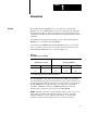
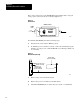
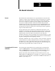
The position of the notch on the AF3 PROM, when installed, must correspond
to the position of the notch shown on the label (Figure 2.2).
Figure 2.2
AF3
Installed
PROM Installation
Release
PROM
Notch
Lock
OFF
ON
11590
1772AF3
DO NOT
ERASE
UP
To install the AF3 PROM, perform the following steps:
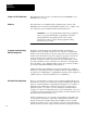
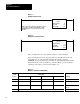
1. Turn the mode select switch to PROG position.
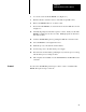
2. To maintain processor memory contents, connect an external battery pack
(Figure 2.3) to the processor with the Mini-Processor Transport Cable (cat.
no. 1772-CD).
Figure 2.3
External
Battery Backup
MiniPLC2/15 Processor
(Cat. No. 1772LV)
Battery Pack
(Cat. No. 1771BB)
MiniProcessor
Transport Cable
(Cat. No. 1772CD)
11182
3. Remove AC power from the I/O chassis.
4. Remove the processor module from the I/O chassis.
5. Check all AF3 PROM pins to ensure they are not bent or contaminated.