Auxiliary Function PROM (Cat. No.
Table of Contents Introduction . . . . . . . . . . . . . . . . . . . . . . . . . . . . . . . . . . . . 1 1 General . . . . . . . . . . . . . . . . . . . . . . . . . . . . . . . . . . . . . . . . . . . Purpose of This Publication . . . . . . . . . . . . . . . . . . . . . . . . . . . . . Audience . . . . . . . . . . . . . . . . . . . . . . . . . . . . . . . . . . . . . . . . . . Programs fo Implementing Machine Diagnostics . . . . . . . . . . . . . . Extended Data Comparison . . . . . . . . . . . . . . . .
Chapter 1 Introduction General The Auxiliary Function PROM (cat. no. 1772-AF3) lets you expand the instruction set of your Mini-PLC-2/15 controller to include the file search and file diagnostic instructions. These instructions are functionally similar to their counterparts in the PLC-2/30 controller but their user-entered instruction format is different. For simplification throughout this manual we refer to the Auxiliary Function PROM (cat. no. 1772-AF3) as the AF3 PROM.
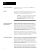
Chapter 1 Introduction Purpose of This Publication This publication shows you how to install and use the AF3 PROM in your Mini-PLC-2/15 controller. Audience We assume that you are familiar with programming and operation of the Mini-PLC-2/15 controller and the Industrial Terminal (cat. no. 1770-T3). We also assume that you are familiar with files and file instructions. WARNING: : Use only Allen-Bradley authorized programming devices to program Allen-Bradley programmable controllers.
Chapter 1 Introduction for its proper bit status at a particular step or operation. The desired standard files can be loaded automatically by a process called a teach routine (described in the application note PLC-2/30 Diagnostics available from PC Systems Division, Application Engineering Department). Program routines for EDC are very similar to a sequencer instruction that compares a file of input words with a file of standard words for a desired status at each particular step.
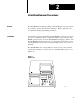
Chapter 2 Installation/Removal Precautions General The AF3 PROM can be damaged during routine handling if proper precautions are not taken to reduce static electricity discharges. Refer to appendix A for recommended handling and handling precautions. Installation You must take special car in handling the AF3 PROM to ensure the pins do not get bent or contaminated. Bent or contaminated pins can prevent proper AF3 PROM operation and use. Store the AF3 PROM in its shipping container.
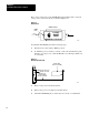
Chapter 2 Installation/Removal Precautions The position of the notch on the AF3 PROM, when installed, must correspond to the position of the notch shown on the label (Figure 2.2). Figure 2.2 AF3 Installed PROM Installation UP 1772 AF3 DO NOT ERASE ON Lock OFF PROM Notch Release 11590 To install the AF3 PROM, perform the following steps: 1. Turn the mode select switch to PROG position. 2. To maintain processor memory contents, connect an external battery pack (Figure 2.
Chapter 2 Installation/Removal Precautions 6. Loosen the screw and lift the PROM door (Figure 2.1). 7. Push the ON tab toward the center to unlock the 28-pin ZIF socket. 8. Remove the PROM if there is one in the socket. 9. Position the AF3 PROM so its notch and arrow face the OFF tab as shown in figure 2.2. 10. Carefully align all pins with their respective sockets. Gently seat the AF3 PROM by pushing it down into its socket. Misaligned pins can bend and miss their sockets. 11.
Chapter 3 File Search Instruction General The auxiliary file search instruction is an output instruction. It searches a file looking for a match of data contained in any file word with data of a specified match word. The instruction starts at the beginning of the file and searches from lowest to highest word address (lowest to highest position number) and from lowest to highest bit number.
Chapter 3 File Search Instruction Figure 3.1 Auxiliary Function Format Execute Aux Function Funtion Number: Data Addr: Rresult Addr: Numbers shown are default values and must be replaced by your values. The number of default address digits originally displayed, 3 or 4, depends on the size of the data table. 01 010 010 Figure 3.
Chapter 3 File Search Instruction You can also load these values in BCD. You can load BCD values into an instruction by means of a file-to-file move instruction. Enter a file-to-file move instruction below the file search instruction. Open the rung by inserting a branch end instruction. Open the rung by inserting a branch end instruction at the beginning of the rung (Figure 3.4). Make the file A address of the file-to-file move instruction the same as data address of the file search instruction.
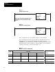
Chapter 3 File Search Instruction Figure 3.5 Example of User Entered Data (BCD) Word Location Bit Location 17 16 15 14 13 12 11 10 07 06 05 04 03 02 01 00 Description 0400 Not used 0 1 0 File Length = 10 0401 Available for 4 1 0 File Address, lower 3 digits 0402 Bit Storage 0 0 0 File Address, upper 3 digits 0403 Application Dependent Match word data Instruction File Address ad Length - You can assign the file to any usable storage location in the data table.
Chapter 3 File Search Instruction The result word also stores control bits of the instruction in addition to the position number. The control bits are stored in bits 17 thru 14. The 3-digit position number is stored as a BCD bit pattern in bits 13 thru 00 (Figure 3.7). Figure 3.
Chapter 3 File Search Instruction Figure 3.8 Example Minimum Logic 010 0405 00 17 Execute Aux Function Funtion Number: Data Addr: Rresult Addr: Function of Control Bits 21 0400 0405 Control bits of the file search instruction are located in the result word, bits 17 thru 14 as follows. Bit: 17 Function: Enable (EN) Description: Your program logic must cause a false-to-true transition of the enable bit for the instruction to operate.
Chapter 3 File Search Instruction Bit: 15 Function: Done (DN) Description: The instruction sets this bit in the same scan that it detects the last match in the file. The done bit remains set until the next false-to-true transition of the enable bit. Then, the instruction resets bits 16 thru 00 of the result word (last state, done, and true bits and the position umber in bits 13 thru 00) and starts the search at the top of the file. The enable bit, bit 17 of this word, is controlled by program logic.
Chapter 3 File Search Instruction If the logic conditions of rung 1 are true, the enable bit, 0405/17, will latch on. Rung 2 will execute the file search instruction. Rung 3 will unlatch the enable bit because its logic conditions are identical to those of rung 1. The file search instruction in rung 4 will see the enable bit reset and will likewise reset the last state bit. Then execution can continue in the next scan. Both file search instructions must be identical. Figure 3.
Chapter 3 File Search Instruction Figure 3.10 Example File Search Logic 0030 RTO 0.1 PR 015 AC 000 030 040 15 17 030 0030 RTR PR 015 AC 000 15 Execute Aux Function Funtion Number: Data Addr: Rresult Addr: 21 0031 0040 0041 PUT 000 0040 G 000 Figure 3.11 Example Data Entry Word Location 0031 0032 0033 0034 0040 0041 . . .
Chapter 4 File Diagnostic Instruction General The auxiliary file diagnostic instruction is an output instruction. It compares data in a file of actual values with another file of user-entered reference values, word-by-word and bit-by-bit. The instruction starts at the beginning of the files and searches from lowest to highest word address and from lowest to highest bit number. When the instruction finds a mismatch, it stops at the word containing the mismatch and sets a bit.
Chapter 4 File Diagnostic Instruction Programming the File Diagnostic Instruction You enter the file search instruction in program logic by pressing the key sequence [SHIFT] [EAF] 20 on the industrial terminal keyboard (series B or later), or [SHIFT] [SCT] 20 on the keyboard of an earlier model that does not contain the [EAF] key. The instruction will appear as shown in Figure 4.1. Figure 4.
Chapter 4 File Diagnostic Instruction Figure 4.
Chapter 4 File Diagnostic Instruction Load data into the five word file associated with the data address as follows. Data Address - The data address is the first address that you entered into the instruction block. The data address is the first of five consecutive addresses into which you load the following data (Figure 4.5).
Chapter 4 File Diagnostic Instruction Figure 4.
Chapter 4 File Diagnostic Instruction Figure 4.
Chapter 4 File Diagnostic Instruction Enabling the Instruction You enable the file diagnostic instruction in program logic using a separate rung that precedes the instruction (Figure 4.8). Address an output or latched output instruction to bit 17 of the file diagnostic instruction’s result address, 0520/17. Program the rung’s input conditions to cycle a false-to-true transition of the output instruction. This initiates a search for the next mismatched word in the file in accordance with your application.
Chapter 4 File Diagnostic Instruction Bit: 14 Function: True (TR) Description: The instruction sets this bit in the same scan that it finds a data mismatch between a word in the file actual values and a word in the file of reference values. The instruction resets this bit in the next scan. you can consider it operation a one-shot. Your program logic should detect the setting of this bit as a condition for initiating the logic associated with a mismatch of data.
Chapter 4 File Diagnostic Instruction Example Programs The following examples of program logic should help you to design your own logic for using the file diagnostic instruction. Search Each Scan - You can program the file diagnostic instruction to search for a mismatch every scan by programming two instructions as follows (Figure 4.9). Figure 4.
Chapter 4 File Diagnostic Instruction data table to accommodate the size of your files (two 128-word data table sections in this example). Enter [SEARCH] [5] [0] followed by the number of data table sections. Enter data into the addresses as shown in Figure 4.11 using [SEARCH] [5] [3]. You can watch the results of the file diagnostic instruction by observing the data in the Get instruction in rung 5. First Get instruction (result word one) shows the error count.
Chapter 4 File Diagnostic Instruction Figure 4.
Chapter 5 Programming Check List General Use the following check list as an aid when entering the file search or file diagnostic instruction into your ladder diagram program. 1. Do you have the correct function number? 2. Is your data table large enough to hold all of your files? 3. Are your address values in octal (BCD 0-7)? 4. Have you made sure that the file of actual values and the file of reference values do not overlap (file diagnostic instruction)? 5.
Appendix A AF3 Recommendations & Precautions AF3 PROM Handling Recommendations and Precautions Recommended precautions include: Handle the AF3 PROM by the case without touching its pins. Use a static-free work station. Wear a conductive wrist strap that has a minimum 200k ohms resistance and is connected to earth ground. Ground tools prior to contacting the AF3 PROM. Connect static-free work station to ground through a minimum 200k ohm resistance.
Index Symbols [SEARCH] [5] [0], 3 8 [SEARCH] [5] [3], 3 2, 4 2, 4 10 Result, 4 5 H Handling precautions, A 1 C Control bits Done, 3 7, 4 8 Enable, 3 6, 4 7 Last state, 3 6, 4 7 True, 3 6, 4 8 D I Installation, 2 1 Instruction file, 3 4 L Loading data, 3 2, 4 3 Data address, 3 3, 4 4 E M Machine diagnostics, 1 3 Enabling the instruction, 3 5, 4 7 Match word, 3 3 Erasing, 1 1 Mini-processor transport cables, 2 2 Errors, response to Address, 3 7, 4 8 Data, 3 7, 4 8 Function number, 3 7, 4 8 Exam
Allen Bradley has been helping its customers improve productivity and quality for 90 years. A B designs, manufactures and supports a broad range of control and automation products worldwide. They include logic processors, power and motion control devices, man machine interfaces and sensors. Allen Bradley is a subsidiary of Rockwell International, one of the world's leading technology companies. With major offices worldwide.