Auxiliary Function PROM (Cat. No.
Table of Contents Introduction . . . . . . . . . . . . . . . . . . . . . . . . . . . . . . . . . . . . 1 1 General . . . . . . . . . . . . . . . . . . . . . . . . . . . . . . . . . . . . . . . . . . . Functions . . . . . . . . . . . . . . . . . . . . . . . . . . . . . . . . . . . . . . . . . Manual's Purpose . . . . . . . . . . . . . . . . . . . . . . . . . . . . . . . . . . . Audience . . . . . . . . . . . . . . . . . . . . . . . . . . . . . . . . . . . . . . . . . . 1 1 1 2 1 2 1 2 Installation . . .
Chapter 1 Introduction General Installation of the Auxiliary Function (AF) PROM (cat. no. 1772-AF1) in your Mini-PLC-2/15 controller lets you expand its mathematical capabilities. For simplification, throughout this manual we refer to the Auxiliary Function PROM (cat. no. 1772-AF1) as the AF1. The AF1 can only be used with the series A Mini-PLC-2/15 processor module, firmware revision 11 or later (cat. no. 1772-LV).
Chapter 1 Introduction Functions The AF1 performs the following arithmetic functions: 6-digit add and subtract 6-digit multiply and divide Square rote Average Standard deviation BCD to binary conversion Binary to BCD conversion Applications These arithmetic functions have applications in various industries such as food processing, machine tool work and material handling. Applications in these industries could be weighing, blending, batch processing, scaling, positioning, test stands, and heat treating.
Chapter 2 Installation General During AF1 installation, take special care not to bend or contaminate the pins. Bent or dirty pins can prevent proper AF1 programming and use. The AF1’s transparent window is covered with the product label to avoid accidental alteration of memory from uv light sources. Do not remove this label. Store the AF1 in its shipping container when not installed in a Mini–PLC–2/15 processor.
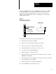
Chapter 2 Installation Installation The AF1 fits into a 28–pin ZIF (zero insertion force) socket, which is located under a hinged door at the lower side of the Mini–PLC–2/15 processor (Figure 2.1). Figure 2.1 PROM Socket 10715 I On the underside of the PROM door is a label that illustrates PROM installation. The notch on the AF1 PROM, when installed, must correspond to the notch shown on the label. Figure 2.2 shows a properly installed AF1. Figure 2.
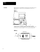
Chapter 2 Installation To access the PROM socket, remove the Mini–PLC–2/15 processor module from the I/O chassis. If you desire to maintain processor memory contents, connect an external battery pack (Figure 2.3) to the processor with the Mini–Processor Transport Cable (cat. no. 1772–CD) prior to removing the module from the chassis. Figure 2.3 External Battery Backup Battery Pack (Cat. No. 1771 BB) Mini PLC 2/15 Processor (Cat. No. 1772 LV) Mini Processor Transport Cable (Cat. No.
Chapter 2 Installation Removal 2 4 To remove the AF1, perform the following steps: 1. Turn the mode select switch to PROG. 2. To maintain processor memory contents connect an external battery pack to the processor with the mini–processor transport cable (Figure 2.3). 3. Remove AC power from the I/O chassis power supply. 4. Remove the processor module from the I/O chassis. 5. Loosen the screw, lift up the PROM door, and push the ON tab in to unlock the socket (Figure 2.2). 6.
Chapter 3 Programming General You access the AF1 by pressing [SHIFT][EAF] (execute auxiliary function) or [SHIFT] [SCT] on the keyboard of your Industrial Terminal (cat. no. 1770-T3). The instruction is an output instruction and may be preceded on a rung by input instructions. Once you enter the function, the block diagram of Figure 3.1 appears on the CRT. To program a specific mathematics function, you would enter the appropriate function number (Table 3.A).
Chapter 3 Programming Table 3.A AF1 Function Numbers Function Number Mathematical Operation 01 Add 02 Subtract 03 Multiply 04 Divide 05 Square root 06 Average 07 Standard deviation 13 BCD to binary conversion 14 Binary to BCD conversion You enter an existent function number and then enter data and result addresses (we will explain this in detail later). The processor then places a number in the data address.
Chapter 3 Programming AF1 Automatic Checks To guard against improper program execution, automatic check routines are incorporated in the AF1. The processor uses these routines to prevent the following: Executing AF1 functions having invalid function addresses Spending so much time executing AF1 functions that the controller neglects its main program and I/O scans Invalid Function Addresses Valid AF1 function addresses include the I/O image table and the data table (except word 027).
Chapter 3 Programming to complete, all other true AF1 function rungs will be “locked out” until sufficient program scans complete the active AF1 function rung. Once started, it completes an AF1 function prior to starting the next AF1 function encountered in the user program which has a true rung condition. Limits the number of enabled AF1 functions in a program to 50. You may include more functions but you must ensure that no more than 50 are enabled at one time.
Chapter 3 Programming To obtain the time required from activation of the input that makes the rung containing the AF1 PROM function true until the correct answer for the function is in the data table, you must add the following times to the values in Table 3.B: Input delay time (from specification for specific input) One program scan time and one I/O scan time multiplied by the number of scans specified in Table 3.B.
Chapter 3 Programming The done bit is rest at the start of an AF1 function and set upon completion. The error bit is a general error flag that indicates overflow and invalid operand or result errors. Individual functions determine the actual state of this bit. Throughout this manual, unused status bits are shown blank for the following reasons: Whether the content of an unused status bit in an input word is 0 or 1 is irrelevant as such bits are ignored in AF1 function execution.
Chapter 3 Programming 2. Enter 01, the function number for AF1 addition. This entry identifies that the function entered is to perform an AF1 addition and that the processor use the data table format shown in Figure 3.2 when executed. Operands 1 and 2 represent the two 6-digit numbers you wish to add. The six digits of operand 1 are represented in BCD by the groups of bits labeled digit 1 through 6. Digit 1 and digit 6 are the most significant and the least significant digits respectively.
Chapter 3 Programming Figure 3.3 AF1 Addition Function Format After Address Entry Bit No.
Chapter 3 Programming Figure 3.
Chapter 3 Programming Error Message If the resultant sum has more than six integers, the error bit (bit 14) is set indicating overflow. AF1 Subtraction Function An AF1 subtraction function operates on two 6-digit BCD numbers and presents the result in a third 6-digit BCD number. (+XXX XXX.) - (+XXX XXX.) = +XXX XXX. How to Enter an AF1 Subtraction Function To program an AF1 subtraction function, perform the following steps: 1.
Chapter 3 Programming Figure 3.6 General AF1 Subtraction Function Word and Digit Format Bit No.
Chapter 3 Programming 3. Enter a data address and result address. If we select a data address of 201 and a result address of 305, the AF1 establishes the data table format shown in Figure 3.7. The data address eventually contains three digits of operand 1. The AF1 reserves the next three higher addresses for digits 4 through 6 of operand 1, and digits 1 through 6 of operand 2.
Chapter 3 Programming 4. Enter values for operands 1 and 2. You can enter these values from the keyboard of your industrial terminal or through ladder diagram functions. Entry of operand 1 = 102746 and operand 2 - 256384 produces the result -153638 when the subtraction function executes. Figure 3.8 shows how the result is stored. Figure 3.
Chapter 3 Programming Figure 3.9 AF1 Subtraction Function Input and Result Display Rungs Execute Aux Function Function Number: Data Addr: Result Addr: 201 202 203 204 G 102 G 746 G 256 G 384 305 306 G 153 G 638 01 201 305 Storage Bit Error Message If the result has more than six integers, the error bit (bit 14) is set indicating overflow. AF1 Multiplication Function An AF1 multiplication function operates on two 6-digit BCD numbers and presents the results in a 12-digit BCD number. (+XXX XXX.
Chapter 3 Programming Figure 3.10 General AF1 Multiplication Function Word and Digit Format Bit No.
Chapter 3 Programming Figure 3.11 AF1 Multiplication Function Format After Address Entry 17 16 15 14 13 12 11 10 Bit No.
Chapter 3 Programming 4. Enter values for operands 1 and 2. You can enter these values from the keyboard of your industrial terminal or through ladder diagram functions. Entry of operand 1 = 000400 and operand 2 = 000200 produces the result 000000080000 (Figure 3.12). Figure 3.12 AF1 Multiplication Function Format After Execution Bit No.
Chapter 3 Programming Figure 3.13 AF2 Multiplication Function Input and Result Display Rungs Execute Aux Function Function Number: Data Addr: Result Addr: 201 202 203 204 G 000 G 400 G 000 G 200 305 306 307 307 G 000 G 000 G 080 G 000 03 201 305 Storage Bit AF1 Division Function An AF1 division function operates on two 6-digit BCD numbers and presents the results in a 12-digit BCD number. (+XXX XXX.) : (+XXX XXX.) = +XXX XXX.
Chapter 3 Programming Figure 3.14 General AF1 Division Function Word and Digit Format Bit No.
Chapter 3 Programming Figure 3.15 AF1 Division Function Format After Address Entry Bit No.
Chapter 3 Programming 4. Enter values for operands 1 and 2. You can enter these numbers from the keyboard of your industrial terminal or through ladder diagram functions. Entry of operand 1 = 000400 and operand 2 = 000200 produces the result 000002.000000 (Figure 3.16). Figure 3.16 AF1 Division Function Format After Execution Bit No.
Chapter 3 Programming Figure 3.17 AF1 Division Function Input and Result Display Rungs Execute Aux Function Function Number: Data Addr: Result Addr: 201 202 203 204 G 000 G 400 G 000 G 200 305 306 307 310 G 000 G 002 G 080 G 000 04 201 305 Storage Bit Error Message If you divide by zero, the error bit (bit 14) is set and the result reads zero.
Chapter 3 Programming Figure 3.18 General AF1 Square Root Function Word and Digit Format Bit No.
Chapter 3 Programming 4. Enter the value for the operand. You can enter the value from the keyboard of your industrial terminal or through ladder diagram functions. Entry of operand = 144 produces the result 12 when the square root function executes. Figure 3.20 shows how the result is stored. The result is accurate to +0.01. Figure 3.20 AF1 Square Root Function Format After Execution Bit No.
Chapter 3 Programming AF1 Average Function The AF1 average function determines the average of a group of N three digit integers. The numbers are in BCD format. x 1x 1x 1. ) x 2x 2x 2x 2. ) x 3x 2x 2. ) AAAx Nx Nx Nx N. + xxx.xxx N The result is a 6 digit number composed of a 3-digit integer and a 3-digit decimal fraction. The maximum number of values you can average is 999 or is limited by the data table area available.
Chapter 3 Programming Figure 3.22 General AF1 Average Function Word and Digit Format Bit No.
Chapter 3 Programming Figure 3.23 AF1 Average Function Format After Address Entry Bit No.
Chapter 3 Programming Figure 3.24 AF1 Average Function Format After Execution Bit No. Number of Inputs 17 16 15 14 13 12 11 10 7 6 5 4 3 2 1 0 Word 0 0 3 200 Data Address Input 1 S (0) 4 1 3 201 Input 2 S (0) 2 3 5 202 Input 3 S (0) 1 2 1 203 2 5 6 Result Address 305 3 3 3 306 E S D ER (0) (0) (1) (0) Result 11587 Entry and Display of Input and Result Values Figure 3.25 shows one method you can use to enter values and display results of an AF1 average function.
Chapter 3 Programming Error Message If you insert a zero for the number of values to be averaged, the error bit (bit 14) is set and the result reads zero. AF1 Standard Deviation Function The AF1 standard deviation function determines the standard deviation of 3digit BCD numbers giving a 6-digit result with an implied decimal point after the third digit. The maximum number of values you can handle is 999 or is limited by the data table area available.
Chapter 3 Programming Figure 3.26 General AF1 Standard Deviation Function Word and Digit Format Bit No.
Chapter 3 Programming Figure 3.27 General AF1 Deviation Function Format After Address Entry Bit No.
Chapter 3 Programming Figure 3.28 AF1 Standard Deviation Function Format After Execution Bit No.
Chapter 3 Programming Figure 3.29 AF1 Standard Deviation Function Input and Result Display Rungs Execute Aux Function Function Number: Data Addr: Result Addr: 200 G 003 201 G 200 305 306 G 000 G 816 202 G 201 203 G 202 07 201 305 Storage Bit AF1 BCD to Binary Conversion Function The AF1 BCD (binary coded decimal) to binary conversion function converts a BCD number (from 0 to 4095) into a 12-bit binary number.
Chapter 3 Programming Figure 3.30 General AF1 BCD to Binary Conversion Function Word and Digit Format Bit No.
Chapter 3 Programming 4. Enter the operand. You can enter the operand from the keyboard of your industrial terminal or through ladder diagram functions. If we choose to enter 4095, the largest BCD number that we can convert to a 12 bit binary number, we obtain the data tale configuration shown in Figure 3.32. Figure 3.32 AF1 BCD to Binary Conversion Function Format After Execution Bit No.
Chapter 3 Programming Error Message If you enter a BCD number larger than 4095, the error bit (bit 14) is set and the result reads zero. AF1 Binary to BCD Conversion Function The AF1 binary to BCD conversion function converts a 12-bit binary number to a BCD number (from 0 to 4095). How to Enter an AF1 Binary to BCD Conversion Function To program an AF1 binary to BCD conversion function, perform the following steps: 1. Press [SHIFT] [EAF] or [SHIFT] [SCT] on the keyboard of your industrial terminal.
Chapter 3 Programming 3. Enter a data address and a result address. If we choose a data address of 200 and a result address of 300, the data table format is as shown in Figure 3.35. Bits 0 through 13 of word 200 are reserved for the operand (the 12-bit binary number we want to convert to BCD). The result address, 300, contains the most significant three digits of the resulting BCD number. The least significant three digits reside in the next higher address, 301.
Chapter 3 Programming Entry and Display of Input and Result Values Figure 3.37 shows one method for inserting input values and displaying inputs and results of an AF1 binary to BCD conversion function. Although there are other methods for accomplishing this, we chose get instructions. The first rung requests an AF1 binary to BCD conversion function. The top branch of the second rung shows the binary number (in the hexadecimal notation FFF) that we want converted to BCD.
Chapter 3 Programming Figure 3.
Index Symbols **Empty**, 3 25 E Enable Bit, 3 5 Error bit, 3 6 A Accuracy, 3 6 Addition, 3 6 Address Data, 3 2, 3 7 Invalid, 3 3 Result, 3 2, 3 7 Valid, 3 3 Error messages, 3 5 Execution time, 3 3 F Function numbers, 3 1, 3 2 Function sequence, 3 2 Functions, 1 2 AF1 (PROM), 1 1 Applications, 1 2 Automatic checks, 3 3 Average function, 3 25 B BCD to binary, 3 33 Binary to BCD, 3 36 Bits, 3 5 Done, 3 5 Enable, 3 5 Error, 3 5 Unused, 3 6 bits, Sign, 3 5 C Checks, 3 3 Result addresses, 3 3 Scan Time, 3
I–2 Index S U Sign bit, 3 5, 3 38 Ultraviolet LIght, 1 1 Square root, 3 22 Unuse bits, 3 6 Standard deviation function, 3 29 Static electricity, 2 1 T Time-execution, 3 3 W Word arrangement, 3 5
Allen Bradley has been helping its customers improve productivity and quality for 90 years. A B designs, manufactures and supports a broad range of control and automation products worldwide. They include logic processors, power and motion control devices, man machine interfaces and sensors. Allen Bradley is a subsidiary of Rockwell International, one of the world's leading technology companies. With major offices worldwide.