
Manual


A Practical Example of ControlNet Concepts
B–2
Publication
1771-6.5.123 – May 1996
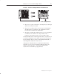
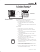
• power supply modules do not take up I/O image space if
placed in the higher numbered slots in the chassis. The adapter
will scan I/O space from the leftmost slot to the rightmost slot,
so any power supply modules or nondiscrete modules are used
most efficiently if placed in the right side of the chassis.
• ATTENTION: It is possible to have only 1/2 of a 32-point
I/O module function since you can configure the map table to
a single word (16-bits), when a 32-point module requires 2
words.
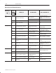
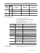
1771–ACNR APPENDIX EXAMPLE Mon Apr 10, 1995 Page 3
Processor/Channel Status PLC–5/40C File ACNEXMPL Channel
Channel Overview
Channel 0: SYSTEM (POINT–TO–POINT)
Channel 1A: DH+
Channel 1B: SCANNER MODE
Channel 2: CONTROLNET
Channel 3A: N/A
£
1771–ACNR APPENDIX EXAMPLE Mon Apr 10, 1995 Page 8
Processor/Channel Status PLC–5/40C File ACNEXMPL Channel 2
ControlNet – Node Info MONITOR
Channel 2 Configuration NODE 1
Diagnostics file: N10 Network Update Time(ms): 5
Coax Repeaters in Series: 0 Scheduled Bandwidth Usage: 10
Fiber Repeater Pairs: 0 Media Redundancy Usage: A Only
Maximum Scheduled Node: 10
Node Node Type Series/Revision Status
1 PLC–5/40C C/G ACTIVE
4 1771–ACNR A/A ACTIVE
£
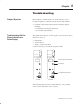
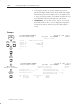
Channel
Overview
6200
Main Menu
General
Utility
F3
Online
Program
Offline
Program
F1
F7
or
F4
Channel
Configuration
F5
(Monitor)
Move cursor to
Channel 2: ControlNet
E
xa
mp
le