
Manual


Appendix
B
Publication
1771-6.5.123 – May 1996
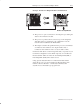
A Practical Example of
ControlNet Concepts
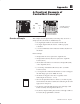
01234567
I/O Chassis Slot Number
PLC-5/40C
01234567
1771-VHSC
1771-VHSC
1771 8 Point In
1771 8 Point In
1771 8 Point Out
1771-P4S
Node
4
Empty
Empty
Map
File
Size
I:10 1
O:23 2
1771-A2B Chassis set
for 2-slot addressing
This example uses the physical layout and map entry screen for a
simple system as shown above. W
ith this layout:
• any legal input module in slots 0 and 1 will be read
• any legal output module in slots 0 to 3 will be properly
controlled
• you can communicate with nondiscrete modules anywhere in
the chassis
In this example:
• the input file size is not equal to the output file size
• the input file location (I:10) is not equal to the output file
location (O:23)
• the module node address is not related to the input file (I:10)
or the output file (O:23)
• you can map odd numbered file sizes (I:10 = 1) and file
locations (O:23)
• you can perform nondiscrete file transfers to slots not mapped
into I/O image space (1771-VHSC in slot 4)
• the chassis is mapped as slots 0 to 7 regardless of the
addressing mode used (2, 1, or 1/2)
• all 1771 I/O placement rules for discrete (8, 16 and 32 point)
and nondiscrete modules as defined for addressing modes still
apply (refer to chapter 3).
• any discrete output modules placed in slots 4 through 7 will
behave as if they are being written all zeroes
• any discrete input modules placed in slots 2 through 7 will not
be read by the programmable controller
Ov
er
vi
e
w of E
xa
mp
le